 = 0x688 = 6*256+8*16+8*1 = 1672
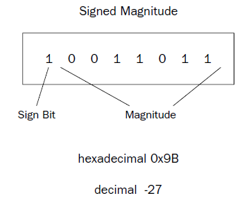 One problem with the signed magnitude method is that there are two different ways to express a zero
value: 00000000 (decimal +0) and 10000000 (decimal -0). This can complicate some mathematical processes.
Also, arithmetic using signed magnitude numbers is complicated, as adding and subtracting simple
signed integers cannot be done in the same way as unsigned numbers. For example, doing a simple
binary addition of the values 00000001 (decimal 1) and 10000001 (decimal –1) produces 10000010 (decimal
–2), which is not the correct answer. Different arithmetic instructions for signed integers and
unsigned numbers would be required on the processor.
One problem with the signed magnitude method is that there are two different ways to express a zero
value: 00000000 (decimal +0) and 10000000 (decimal -0). This can complicate some mathematical processes.
Also, arithmetic using signed magnitude numbers is complicated, as adding and subtracting simple
signed integers cannot be done in the same way as unsigned numbers. For example, doing a simple
binary addition of the values 00000001 (decimal 1) and 10000001 (decimal –1) produces 10000010 (decimal
–2), which is not the correct answer. Different arithmetic instructions for signed integers and
unsigned numbers would be required on the processor.
0x402008
0x402010
//32 byte each element
(gdb)
(gdb) x/40b &data2
0x402014
0x40201c
0x402024
0x40202c
0x402034
//64 bit each element
(gdb)
(gdb) x/5d &data1
0x402000
0x402010
(gdb)
0x402014
0x402024
//WRONG , x/d NOT SUFFICIENT. the debugger didn’t know how to handle displaying the values using just the x/d command.
If you want to display quadword signed integer values in the debugger, you must use the gd option
(gdb)
(gdb) x/5gd &data2
0x402014
0x402024
0x402034
(gdb)
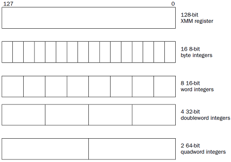
SIMD Integers
The Intel Single Instruction Multiple Data (SIMD) technology provides additional ways to define integers
These new integer types enable the processor to perform arithmetic operations on a group of multiple integers simultaneously.
The SIMD architecture uses the packed integer data type. A packed integer is a series of bytes that can represent more than one integer value. Mathematical operations can be performed on the series of bytes as a whole, working on the individual integer values within the series in parallel.
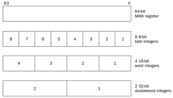
MMX integers
The Multimedia Extension (MMX) technology introduced in the Pentium MMX and Pentium II processors provided three new integer types:
❑ 64-bit packed byte integers
❑ 64-bit packed word integers
❑ 64-bit packed doubleword integers
Each of these data types provides for multiple integer data elements to be contained (or packed) in a single 64-bit MMX register.
the MMX registers are mapped to the FPU registers.
we need to save any data stored in the FPU registers in memory before using any MMX register instructions.
we can use the MOVQ instruction to move data into an MMX register, but we must decide which of the three packed integer formats . The format of the MOVQ instruction is
movq source, destination
where source and destination can be an MMX register, an SSE register, or a 64-bit memory location
(although you cannot move MMX integers between memory locations).
# mmxt
.section .data
values1:
.int 1, -1 # int = 32 bit = double word
values2:
.byte 0x10, 0x05, 0xff, 0x32, 0x47, 0xe4, 0x00, 0x01 #HEX
.section .text
.globl _start
_start:
nop
movq values1, %mm0
movq values2, %mm1
movl $1, %eax
movl $0, %ebx
//int $0x80 in Linux
int $0x21
(gdb) print $mm0
$1 = {uint64 = -4294967295, v2_int32 = {1, -1}, v4_int16 = {1, 0, -1, -1}, v8_int8 = {1, 0, 0, 0, -1, -1, -1, -1}}
(gdb) print/t $mm0
$3 = {uint64 = 1111111111111111111111111111111100000000000000000000000000000001, v2_int32 = {1, 11111111111111111111111111111111}, v4_int16 = {1, 0, 1111111111111111, 1111111111111111}, v8_int8 = {1, 0, 0, 0, 11111111, 11111111, 11111111, 11111111}} (gdb)
(gdb) print/x $mm0
$2 = {uint64 = 0xffffffff00000001, v2_int32 = {0x1, 0xffffffff}, v4_int16 = {0x1, 0x0, 0xffff, 0xffff}, v8_int8 = {0x1, 0x0, 0x0, 0x0, 0xff, 0xff, 0xff, 0xff}}
(gdb) print/x $mm1
$3 = {uint64 = 0x100e44732ff0510, v2_int32 = {0x32ff0510, 0x100e447}, v4_int16 = {0x510, 0x32ff, 0xe447, 0x100},
v8_int8 = {0x10, 0x5, 0xff, 0x32, 0x47, 0xe4, 0x0, 0x1}}
# mmxtd
.section .data
values1:
.int 1, -1 # int = 32 bit = double word
values2:
.byte 16, 5, 255, 50, 71, 228, 0, 1 #DEC
.section .text
.globl _start
_start:
nop
movq values1, %mm0
movq values2, %mm1
movl $1, %eax
movl $0, %ebx
//int $0x80 in Linux
int $0x21
C:\>as -gstabs -o users\rnz\desktop\xmtd.o users\rnz\desktop\xmtd.s
Assembler messages:
Error: can't open users\rnz\desktop\xmtd.s for reading: No such file or directory
C:\>as -gstabs -o users\rnz\desktop\mmxtd.o users\rnz\desktop\mmxtd.s
C:\>ld -o users\rnz\desktop\mmxtd.exe users\rnz\desktop\mmxtd.o
C:\>gdb -q users\rnz\desktop\mmxtd.exe
Reading symbols from users\rnz\desktop\mmxtd.exe...done.
(gdb) break 1 # in linux break *_start+1
Breakpoint 1 at 0x401000: file users\rnz\desktop\mmxtd.s, line 1.
(gdb) run
Starting program: C:\users\rnz\desktop\mmxtd.exe
[New Thread 7976.0x36d4]
Breakpoint 1, start () at users\rnz\desktop\mmxtd.s:10
10 nop
(gdb) s
11 movq values1, %mm0
(gdb) s
12 movq values2, %mm1
(gdb) s
13 movl $1, %eax
(gdb) s
14 movl $0, %ebx
(gdb) s
16 int $0x21
(gdb) print $mm0
$1 = {uint64 = -4294967295, v2_int32 = {1, -1}, v4_int16 = {1, 0, -1, -1}, v8_int8 = {1, 0, 0, 0, -1, -1, -1, -1}}
(gdb) print/x $mm0
$5 = {uint64 = 0xffffffff00000001, v2_int32 = {0x1, 0xffffffff}, v4_int16 = {0x1, 0x0, 0xffff, 0xffff}, v8_int8 = {0x1, 0x0, 0x0, 0x0, 0xff, 0xff, 0xff, 0xff}}
(gdb) print $mm1
$3 = {uint64 = 72308588487312656, v2_int32 = {855573776, 16835655}, v4_int16 = {1296, 13055, -7097, 256}, v8_int8 = {16, 5, -1, 50, 71, -28, 0, 1}}
(gdb) print/x $mm1
$4 = {uint64 = 0x100e44732ff0510, v2_int32 = {0x32ff0510, 0x100e447}, v4_int16 = {0x510, 0x32ff, 0xe447, 0x100}, v8_int8 = {0x10, 0x5, 0xff, 0x32, 0x47, 0xe4, 0x0, 0x1}}
(gdb) print/f $mm1
$21 = {uint64 = 7.697470564745318e-304, v2_int32 = {2.96882092e-08, 2.3673668e-38}, v4_int16 = {1296, 13055, -7097, 256}, v8_int8 = {16, 5, -1, 50, 71, -28, 0, 1}}
(gdb) print/f $mm0
$22 = {uint64 = -nan(0xfffff00000001), v2_int32 = {1.40129846e-45, -nan(0x7fffff)}, v4_int16 = {1, 0, -1, -1}, v8_int8 = {1, 0, 0, 0, -1, -1, -1, -1}}
(gdb)
// STXR are the FPU Registers counterparts of MMX
// mm0 register is mapped to the first FPU register, st0r
// the same for the other 7 registers
SSE integers
The Streaming SIMD Extensions (SSE) technology (also described in Chapter 2) provides eight 128-bit
XMM registers (named XMM0 through XMM7) for handling packed data. The SSE2 technology (introduced in the Pentium 4 processor) provides four additional packed signed integer data types:
❑ 128-bit packed byte integers
❑ 128-bit packed word integers
❑ 128-bit packed doubleword integers
❑ 128-bit packed quadword integers
# xmm01
.section .data
valu0:
.int 1, -1, 0, 135246 # 128 bit
valu1:
.quad 1, -1 # 128 bit
.section .text
//.globl _start
//_start:
nop
movdqu valu0, %xmm0
movdqu valu1, %xmm1
movl $1, %eax
movl $0, %ebx
//int $0x80
int $0x21
C:\>as -gstabs -o users\rnz\desktop\xmm01.o users\rnz\desktop\xmm01.s
C:\>ld -o users\rnz\desktop\xmm01.exe users\rnz\desktop\xmm01.o
C:\>gdb -q users\rnz\desktop\xmm01.exe
Reading symbols from users\rnz\desktop\xmm01.exe...done.
(gdb) break 1
Breakpoint 1 at 0x401000: file users\rnz\desktop\xmm01.s, line 1.
(gdb) run
Starting program: C:\users\rnz\desktop\xmm01.exe
[New Thread 1044.0x2f5c]
Breakpoint 1, ?? () at users\rnz\desktop\xmm01.s:10
10 nop
(gdb) s
11 movdqu valu0, %xmm0
(gdb) s
12 movdqu valu1, %xmm1
(gdb) s
13 movl $1, %eax
(gdb) s
14 movl $0, %ebx
(gdb) s
16 int $0x21
(gdb) print $xmm0
$1 = {v4_float = {1.40129846e-45, -nan(0x7fffff), 0, 1.89520012e-40}, v2_double = {-nan(0xfffff00000001), 2.8699144274488922e-309}, v16_int8 = {1, 0, 0, 0, -1, -1, -1, -1, 0, 0, 0, 0, 78, 16, 2, 0}, v8_int16 = {1, 0, -1, -1, 0, 0, 4174, 2}, v4_int32 = {1, -1, 0, 135246}, v2_int64 = {-4294967295, 580877146914816}, uint128 = 10715292067404213048920514521726977}
(gdb) print/x $xmm0
$2 = {v4_float = {0x0, 0x0, 0x0, 0x0}, v2_double = {0x8000000000000000, 0x0}, v16_int8 = {0x1, 0x0, 0x0, 0x0, 0xff, 0xff, 0xff, 0xff, 0x0, 0x0, 0x0, 0x0, 0x4e, 0x10, 0x2, 0x0}, v8_int16 = {0x1, 0x0, 0xffff, 0xffff, 0x0, 0x0, 0x104e, 0x2}, v4_int32 = {0x1, 0xffffffff, 0x0, 0x2104e}, v2_int64 = {0xffffffff00000001, 0x2104e00000000}, uint128 = 0x2104e00000000ffffffff00000001}
(gdb) print/t $xmm0
$3 = {v4_float = {0, 0, 0, 0}, v2_double = {1000000000000000000000000000000000000000000000000000000000000000, 0}, v16_int8 = {1, 0, 0, 0, 11111111, 11111111, 11111111, 11111111, 0, 0, 0, 0, 1001110, 10000, 10, 0}, v8_int16 = {1, 0, 1111111111111111, 1111111111111111, 0, 0, 1000001001110, 10}, v4_int32 = {1, 11111111111111111111111111111111, 0, 100001000001001110}, v2_int64 = {1111111111111111111111111111111100000000000000000000000000000001, 10000100000100111000000000000000000000000000000000}, uint128 = 100001000001001110000000000000000000000000000000001111111111111111111111111111111100000000000000000000000000000001}
(gdb) print/f $xmm0
$4 = {v4_float = {1.40129846e-45, -nan(0x7fffff), 0, 1.89520012e-40}, v2_double = {-nan(0xfffff00000001), 2.8699144274488922e-309}, v16_int8 = {1, 0, 0, 0, -1, -1, -1, -1, 0, 0, 0, 0, 78, 16, 2, 0}, v8_int16 = {1, 0, -1, -1, 0, 0, 4174, 2}, v4_int32 = {1.40129846e-45, -nan(0x7fffff), 0, 1.89520012e-40}, v2_int64 = { -nan(0xfffff00000001), 2.8699144274488922e-309}, uint128 = 10715292067404213048920514521726977}
(gdb) print $xmm1
$5 = {v4_float = {1.40129846e-45, 0, -nan(0x7fffff), -nan(0x7fffff)}, v2_double = {4.9406564584124654e-324, -nan(0xfffffffffffff)}, v16_int8 = {1, 0, 0, 0, 0, 0, 0, 0, -1, -1, -1, -1, -1, -1, -1, -1}, v8_int16 = {1, 0, 0, 0, -1, -1, -1, -1}, v4_int32 = {1, 0, -1, -1}, v2_int64 = {1, -1}, uint128 = 340282366920938463444927863358058659841}
(gdb) print/x $xmm1
$6 = {v4_float = {0x0, 0x0, 0x0, 0x0}, v2_double = {0x0, 0x8000000000000000}, v16_int8 = {0x1, 0x0, 0x0, 0x0, 0x0, 0x0, 0x0, 0x0, 0xff, 0xff, 0xff, 0xff, 0xff, 0xff, 0xff, 0xff}, v8_int16 = {0x1, 0x0, 0x0, 0x0, 0xffff, 0xffff, 0xffff, 0xffff}, v4_int32 = {0x1, 0x0, 0xffffffff, 0xffffffff}, v2_int64 = {0x1, 0xffffffffffffffff}, uint128 = 0xffffffffffffffff0000000000000001}
(gdb) print/t $xmm1
$7 = {v4_float = {0, 0, 0, 0}, v2_double = {0, 1000000000000000000000000000000000000000000000000000000000000000}, v16_int8 = {1, 0, 0, 0, 0, 0, 0, 0, 11111111, 11111111, 11111111, 11111111, 11111111, 11111111, 11111111, 11111111}, v8_int16 = {1, 0, 0, 0, 1111111111111111, 1111111111111111, 1111111111111111, 1111111111111111}, v4_int32 = {1, 0, 11111111111111111111111111111111, 11111111111111111111111111111111}, v2_int64 = {1, 1111111111111111111111111111111111111111111111111111111111111111}, uint128 = 11111111111111111111111111111111111111111111111111111111111111110000000000000000000000000000000000000000000000000000000000000001}
(gdb) print/f $xmm1
$8 = {v4_float = {1.40129846e-45, 0, -nan(0x7fffff), -nan(0x7fffff)}, v2_double = {4.9406564584124654e-324, -nan(0xfffffffffffff)}, v16_int8 = {1, 0, 0, 0, 0, 0, 0, 0, -1, -1, -1, -1, -1, -1, -1, -1}, v8_int16 = {1, 0, 0, 0, -1, -1, -1, -1}, v4_int32 = {1.40129846e-45, 0, -nan(0x7fffff), -nan(0x7fffff)}, v2_int64 = { 4.9406564584124654e-324, -nan(0xfffffffffffff)}, uint128 = 340282366920938463444927863358058659841}
(gdb)
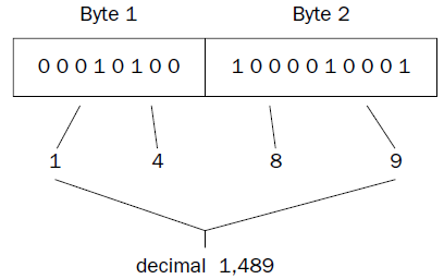
Each BCD value is an unsigned 8-bit integer, with a value range of 0 to 9.
The 8-bit values higher than 9 are considered invalid in BCD.
Bytes containing BCD values are combined to represent decimal digits.
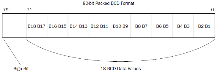
FPU BCD values
The FPU registers can be used for BCD arithmetic operations within the FPU.
The FPU contains eight 80- bit registers (ST0 through ST7), which can also be used to hold 80-bit BCD values. The BCD values are stored using the lower 9 bytes, using packed BCD format, two BCD values per byte (producing 18 BCD digits). The last byte of the FPU register is mostly unused, with the exception of the highest-order bit. This bit is used as a sign indicator ' 1 ' indicates a negative BCD value, and a ' 0 ' indicates a positive value.
fbld source
where source is an 80-bit memory location.
# bcdtest
.section .data
data1:
.byte 0x34, 0x12, 0x00, 0x00, 0x00, 0x00, 0x00, 0x00, 0x00, 0x00
data2:
.int 2
.section .text
.globl _start
_start:
nop
fbld data1
fimul data2
fbstp data1
movl $1, %eax
movl $0, %ebx
int $0x80
This program creates a simple BCD value representing the decimal value 1,234 at the memory location defined by the label data1 (remember that Intel uses little-endian notation).
The FBLD instruction is used to load the value into the top of the FPU register stack (ST0).
The FIMUL instruction is used to multiply the ST0 register by the integer value at the data2 memory location.
Finally, the FBSTP instruction is used to move the new value on the stack back into the data1 memory location.
(gdb) x/10b &data1
0x8049094
0x804909c
The BCD value for 1,234 is loaded at the data1 memory location. Next, step through the FBLD instruction, and check the value in the ST0 register using the info all command:
(gdb)
12 fimul data2
(gdb) info all # INFO ALL
st0 1234 (raw 0x40099a40000000000000)
When you find the ST0 register value in the list of registers, it should show that it is loaded with the decimal value 1,234. You may notice, however, that the hexadecimal value of the register is not in 80-bit packed BCD format. Remember that the BCD value is converted to the floating-point representation while in the FPU.
Now step through the next instruction (FIMUL) and view the registers again:
(gdb) s
13 fbstp data1
(gdb) info all # INFO ALL
st0 2468 (raw 0x400a9a40000000000000)
Indeed, the value in the ST0 register was multiplied by 2. The last step should place the value in ST0 back into the data1 memory location. You can check that by displaying the memory location:
(gdb) x/10b &data1
0x8049094
0x804909c
new value was placed in the data1 memory location, back in BCD format.
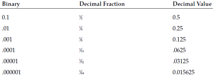
Floating-Point Numbers
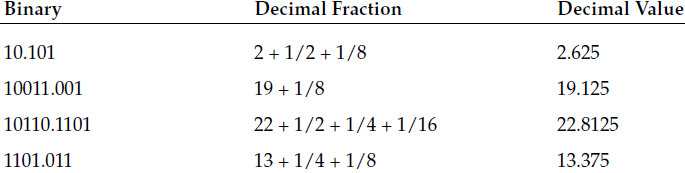
In the decimal world, you are used to seeing values such as 0.159. What this value represents is 0 + 1⁄10 + 5⁄100 + 9⁄1000.
The same principle applies to the binary world.
The coefficient value 1.0101 multiplied by the exponent 2^2 would yield the binary value 101.01, which represents the decimal whole number 5, plus the fraction 0⁄2 + 1/4. This yields the decimal value 5.25.
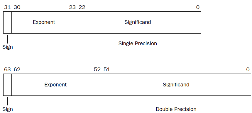
IEEE Standard 754 floating-point formats are used universally to represent real numbers in computer systems.
Intel and AMD have adopted this standard in the IA-32 platform for representing floating-point values.
❑ A sign
❑ A significand
❑ An exponent
The sign bit denotes if the value is negative or positive. A one in the sign bit denotes a negative value, and a zero denotes a positive value.
The exponent is modified to accommodate how many bit positions have been shifted to accomplish this (similar to the scientific notation method). This means that in a normalized value, the significand is always comprised of a one and a binary fraction. The exponent represents the exponent part of the floating-point number. Because the exponent value can be positive or negative, it is offset by a bias value. This ensures that the exponent field can only be a positive unsigned integer. It also limits the minimum and maximum exponent values available for use in the format.
The significand part represents the coefficient (or mantissa) of the floating-point number. The coefficient can be either normalized or denormalized. When a binary value is normalized, it is written with a one before the decimal point.
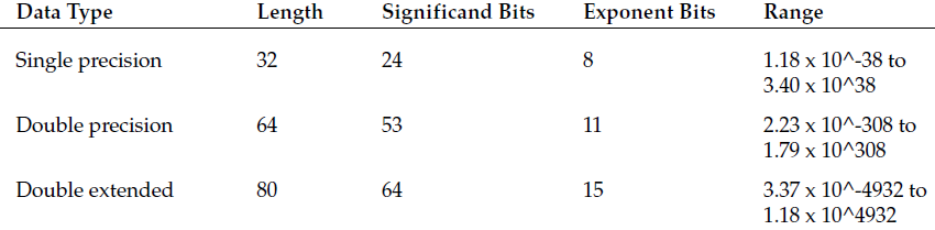
The IEEE Standard 754 defines two sizes of floating-point numbers:
❑ 32-bits (single-precision)
❑ 64-bits (double-precision)
then
# fpux
.section .data
value1:
.float 12.34 # directive to create 32-bit singleprecision values
value2:
.double 2353.631 # directive is used to create 64-bit double-precision values
.section .bss
.lcomm data, 8 # label that points to an empty buffer in memory that will be used to transfer a double-precision floating-point value
.section .text
.globl _start
_start:
nop
flds value1 # instruction for loading single-precision floating-point numbers
fldl value2 # instruction for loading double-precision floating-point numbers
fstl data # instruction for retrieving the top value on the FPU register stack and placing the value in a memory location
# FSTS for single-precision numbers and FSTL for double-precision numbers
movl $1, %eax
movl $0, %ebx
int $0x80
fpux.s
fpux.o
fpux.exe
C:\>gdb -q users\rnz\desktop\fpux.exe
Reading symbols from users\rnz\desktop\fpux.exe...done.
(gdb) break 1
Breakpoint 1 at 0x401000: file users\rnz\desktop\fpux.s, line 1.
(gdb) run
Starting program: C:\users\rnz\desktop\fpux.exe
[New Thread 10236.0x4624]
Breakpoint 1, start () at users\rnz\desktop\fpux.s:12
12 nop
(gdb) s
13 flds value1
(gdb) x/4b &value1
0x402000
(gdb) x/4 &value1
0x402000
(gdb) x/4t &value1
0x402000
(gdb) x/gf &value2
0x402004
(gdb) s
14 fldl value2
(gdb) print $st0
$1 = 12.340000152587890625 # FIRST ELEMENT IS LOADED IN LOWEST ADDRESS REGISTER
(gdb) print $st1
$2 = 0
(gdb) s
15 fstl data
(gdb) print $st0
$3 = 2353.63099999999985812 # LAST ELEMENT IS LOADED IN LOWEST ADDRESS REGISTER
(gdb) print $st1
$4 = 12.340000152587890625 # PREVIOUS ELEMENT SHIFTS IN NEXT HIGHER ADDRESS REGISTER
(gdb) x/gf &data
0x403000 : 0 # after indtruction FSTL data still set to zero
(gdb) s
16 movl $1, %eax
(gdb) x/gf &data
0x403000 : 2353.6309999999999 # now after movl $1 %eax , fpu stack pointer retrieve last element pushed in st0
The FSTL instruction loaded the value in the ST0 register to the memory location pointed to by the data label.