/*personal elementary notes of renzo diomedi*/
~ 00000000 ~
0 0000
1 0001
2 0010
3 0011
4 0100
5 0101
6 0110
7 0111
8 1000
9 1001
a 1010
b 1011
c 1100
d 1101
e 1110
f 1111
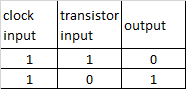
A Transistor is a switch that can be ON or OFF.
an open transistor, therefore without contact between the conductors, is not crossed by electricity, provides the binary number = 0
while a closed transistor, then with contact between conductors, is traversed by current, provides the binary number = 1
The Intel pentium4 microchip has over 43,000,000 transistors, AMD athlon has at least 37,000,000.
The Oscillator, ie the Clock, adjusts the working speed of the computer, more beats = greater speed, measured in megahertz,
i.e millions of beats per second.
the current passing through a transistor can be used to control another transistor. It turns the switch on ON or OFF
to change the status of the second transistor. This configuration is called PORT.
the logic port NOT is composed of a single transistor that takes an Input from the Clock and an Input from another transistor.
this Port produces only one output, which is always the opposite of the input coming from the transistor
different combinations of NOT ports create other logical ports
OR 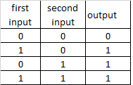
AND 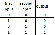
XOR 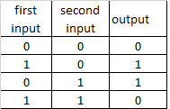
using different combinations of logical ports , the microchip executes the Addition operation from which
all other mathematical operations descend.
the addition is executed through structures called Half-Adder and Full-Adder
a half-adder is made by a port XOR and a port AND which receives both the same Bit in input
eg:
2d + 3d = 10b + 11b
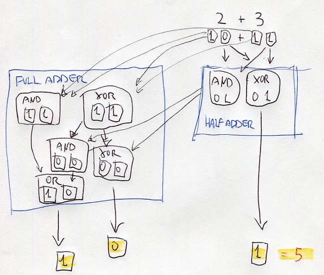
half-adder processes the digits at right using the portd XOR and AND
the resutl of XOR is the digit at right of the final result
the result of AND is the input of ports XOR and AND of the full-adder
also, the full-adder processes the digits at left of thr bits 10 and 10
the results are the inputs of other ports AND and XOR
the results are processed with the results of the half-adder
one of these results is the input of OR
all the results gives the binary number 101 that is 5 on decimal numbers
8f = 8*16^1 + f*16^0 = 143
143 = 143/16 = 8,9375 ; 0,9375*16 = 15=f ; 143d = 8f
2569 = 2569/16 = 160,5625 = 160+(0,5625*16=9) ; 160/16 = 10+(0) ; = A09h
binary number , TWO's Complement
most dignificant digit = 0 = positive
most significant digit = 1 = negative
negative bunary number = inverting bits of positive number + add 1
384 0000000110000000
-384 1111111001111111 +1 = 1111111010000000
absolute value = inverted bits of negative number + add 1
bitwise = bit to bit
Endian refers to the position where the data begins to be processed (written, read on, transmitted/received etc) hence, the beginning of the memory address.
the definition: Endian, creates confusion!
Big Endian - Little Endian
The difference between the two systems is given by the order in which the data bytes (note: NOT BITS!!!) are stored or transmitted in memory address:
big-endian: storage / transmission starting from the most significant byte (largest end) to ending with the least significant;
little endian: storage / transmission starting from the least significant byte (smallest end) to ending with the most significant, is used on
CISC machine such as Intel and AMD processors;
The big-endian order has been chosen as the standard order in many protocols used on the Internet, it is therefore also called the network byte order.
It is used by ARM (advances RISC machine) processors and others Embedded (Special Purpose) microprocessors
Driver:
code to control a specific device. Bios extension. It prevents the Bios ,that resides in a permanent memory, from having to include all the commands
for each hardware component, to avoid to assume enormous dimensions and to become quickly obsolete.
ORTHOGONALITY
Standardization of the sets of the instructions and dimensions of their fields.
Homogeneous blocks.
The ORTHOGONALITY of the instructions indicates
the regularity in the structure directly
of the word that represents an Instruction.
An orthogonal instruction set presents
words of the same length, in which the
size of fields associated with functions
(e.g. OPCODE) are always the
same.
This allows you to have a format of
unique and constant instruction, favoring
the alignment of the same in memory and
hence the processor speed.
IA-32 platform
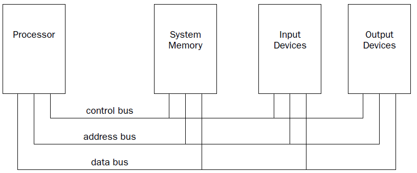
The processor contains the hardware and instruction codes that control the operation of the computer. It
is connected to the other elements of the computer (the memory storage unit, input devices, and output
devices) using three separate buses:
a control bus,
an address bus,
a data bus.
The control bus is used to synchronize the functions between the processor and the individual system
elements. The data bus is used to move data between the processor and the external system elements.
An example of this would be reading data from a memory location. The processor places the memory
address to read on the address bus, and the memory storage unit responds by placing the value stored
in that memory location on the data bus for the processor to access.
The processor itself consists of many components. Each component has a separate function in the processor’s
ability to process data. Assembly language programs have the ability to access and control each
of these elements,
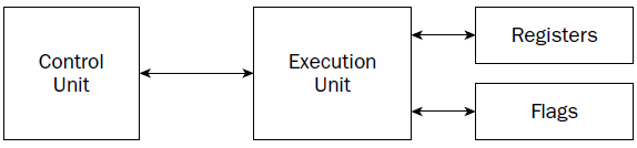
CU
At the heart of the processor is the control unit. The main purpose of the control unit is to control what
is happening at any time within the processor. While the processor is running, instructions must be
retrieved from memory and loaded for the processor to handle. The job of the control unit is to perform
four basic functions:
1. Retrieve instructions from memory.
2. Decode instructions for operation.
3. Retrieve data from memory as needed.
4. Store the results as necessary.
The instruction counter retrieves the next instruction code from memory and prepares it to be processed.
The instruction decoder is used to decode the retrieved instruction code into a micro-operation.
The
MICRO-operation is the code that controls the specific signals within the processor chip to perform the
function of the instruction code.
When the prepared micro-operation is ready, the control unit passes it along to the execution unit for
processing, and retrieves any results to store in an appropriate location.
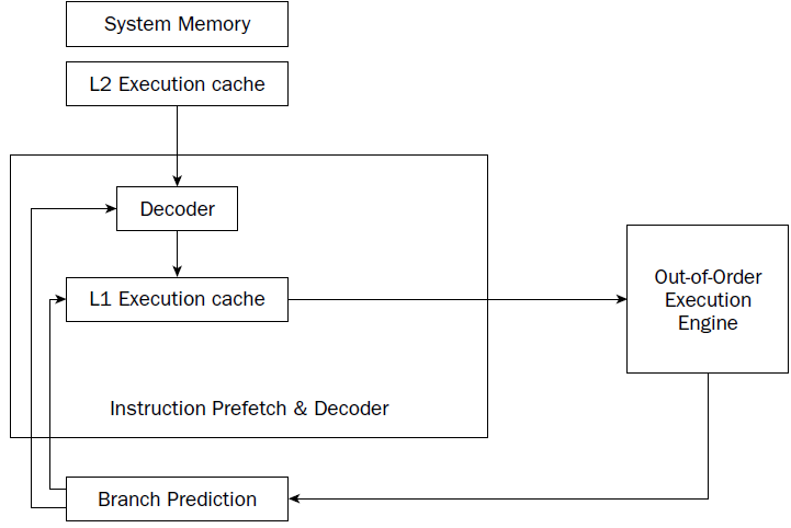
The NetBurst technology incorporates four separate techniques to help speed up processing in
the control unit. Knowing how these techniques operate can help you optimize your assembly language
programs. The NetBurst features are as follows:
❑ Instruction prefetch and decoding
❑ Branch prediction
❑ Out-of-order execution
❑ Retirement
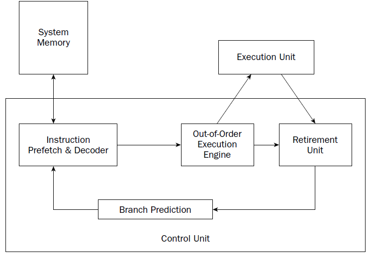
Instruction prefetch and decoding pipeline
Older processors fetched instructions and data directly from system memory as they
were needed by the execution unit. Because it takes considerably longer to retrieve data from memory
than to process it, a backlog occurs, whereby the processor is continually waiting for instructions and
data to be retrieved from memory. To solve this problem, the concept of prefetching was created.
Although the name sounds odd, prefetching involves attempting to retrieve (fetch) instructions and/or
data before they are actually needed by the execution unit. To incorporate prefetching, a special storage
area is needed on the processor chip itself—one that can be easily accessed by the processor, quicker
than normal memory access. This was solved using pipelining.
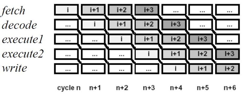
 double pipeline
Pipelining involves creating a memory cache on the processor chip from which both instructions and
data elements can be retrieved and stored ahead of the time that they are required for processing. When
the execution unit is ready for the next instruction, that instruction is already available in the cache and
can be quickly processed.
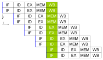
The IA-32 platform implements pipelining by utilizing two (or more) layers of cache. The first cache
layer (called L1) attempts to prefetch both instruction code and data from memory as it thinks it will
be needed by the processor. As the instruction pointer moves along in memory, the prefetch algorithm
determines which instruction codes should be read and placed in the cache. In a similar manner, if data
is being processed from memory, the prefetch algorithm attempts to determine what data elements
may be accessed next and also reads them from memory and places them in cache.
there is no guarantee that the program will
execute instructions in a sequential order. If the program takes a logic branch that moves the instruction
pointer to a completely different location in memory, the entire cache is useless and must be cleared and
repopulated with instructions from the new location.
To help alleviate this problem, a second cache layer was created. The second cache layer (called L2) can
also hold instruction code and data elements, separate from the first cache layer. When the program
logic jumps to a completely different area in memory to execute instructions, the second layer cache can
still hold instructions from the previous instruction location. If the program logic jumps back to the area,
those instructions are still being cached and can be processed almost as quickly as instructions stored in
the first layer cache.
Assembly language programs cannot access the instruction and data caches.
By minimizing branches in programs, you can help speed up the execution of
the instruction codes in your program.
Branch prediction unit
While implementing multiple layers of cache is one way to help speed up processing of program logic, it
still does not solve the problem of “jumpy” programs. If a program takes many different logic branches,
it may well be impossible for the different layers of cache to keep up, resulting in more last-minute
memory access for both instruction code and data elements.
To help solve this problem, the IA-32 platform processors also incorporate branch prediction.
Branch prediction
uses specialized algorithms to attempt to predict which instruction codes will be needed next
within a program branch.
Special statistical algorithms and analysis are incorporated to determine the most likely path traveled
through the instruction code. Instruction codes along that path are prefetched and loaded into the cache
layers.
The Pentium 4 processor utilizes three techniques to implement branch prediction:
❑ Deep branch prediction
❑ Dynamic data flow analysis
❑ Speculative execution
Deep branch prediction enables the processor to attempt to decode instructions beyond multiple
branches in the program. Again, statistical algorithms are implemented to predict the most likely path
the program will take throughout the branches. While this technique is helpful, it is not totally foolproof.
Dynamic data flow analysis performs statistical real-time analysis of the data flow throughout the processor.
Instructions that are predicted to be necessary for the flow of the program but not reached yet by
the instruction pointer are passed to the out-of-order execution core . In addition, any
instructions that can be executed while the processor is waiting for data related to another instruction
are processed.
Speculative execution enables the processor to determine what distant instruction codes not immediately
in the instruction code branch are likely to be required, and attempt to process those instructions,
again using the out-of-order execution engine.
Out-of-order execution engine
The out-of-order execution engine is one of the greatest improvements to the Pentium 4 processor in
terms of speed. This is where instructions are prepared for processing by the execution unit. It contains
several buffers to change the order of instructions within the pipeline to increase the performance of the
control unit.
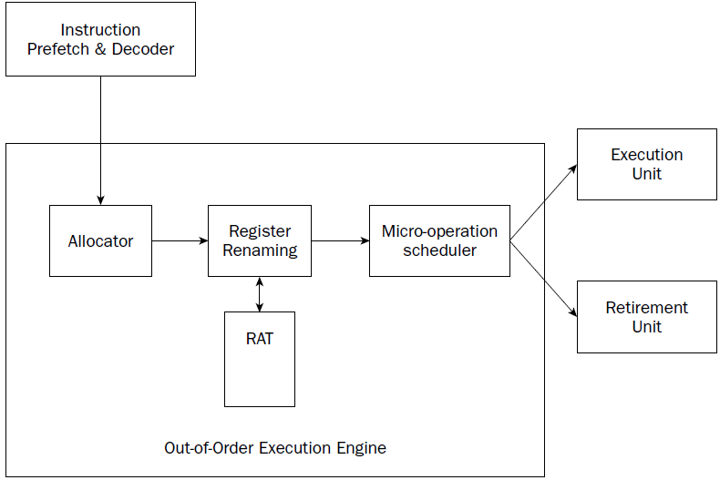
Instructions retrieved from the prefetch and decoding pipeline are analyzed and reordered, enabling
them to be executed as quickly as possible. By analyzing a large number of instructions, the out-of-order
execution engine can find independent instructions that can be executed (and their results saved) until
required by the rest of the program. The Pentium 4 processor can have up to 126 instructions in the outof-
order execution engine at any one time.
There are three sections within the out-of-order execution engine:
❑ The allocator
❑ Register renaming
❑ The micro-operation scheduler
The Allocator is the traffic cop for the out-of-order execution engine.
Its job is to ensure that buffer space is allocated properly for each instruction that the out-of-order execution engine is processing. If a needed
resource is not available, the allocator will stall the processing of the instruction and allocate resources
for another instruction that can complete its processing.
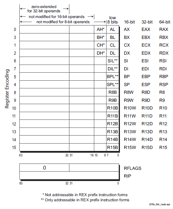
The register renaming section allocates logical registers to process instructions that require register
access. Instead of the eight general-purpose registers available on the IA-32 processor,
the register renaming section contains 128 logical registers. It maps register
requests made by instructions into one of the logical registers, to allow simultaneous access to the same
register by multiple instructions. The register mapping is done using the Register Allocation Table (RAT).
This helps speed up processing instructions that require access to the same register sets.
The micro-operation scheduler determines when a micro-operation is ready for processing by examining
the input elements that it requires. Its job is to send micro-operations that are ready to be processed to
the retirement unit, while still maintaining program dependencies.
The micro-operation scheduler uses
two queues to place micro-operations, in one for micro-operations that require memory access and one
for micro-operations that do not. The queues are tied to dispatch ports. Different types of Pentium processors
may contain a different number of dispatch ports. The dispatch ports send the micro-operations
to the retirement unit.
Retirement unit
The retirement unit receives all of the micro-operations from the pipeline decoders and the out-of-order
execution engine and attempts to reassemble the micro-operations into the proper order for the program
to properly execute.
The retirement unit passes micro-operations to the execution unit for processing in the order that the
out-of-order execution engine sends them, but then monitors the results, reassembling the results into
the proper order for the program to execute.
This is accomplished using a large buffer area to hold micro-operation results and place them in the
proper order as they are required.
When a micro-operation is completed and the results placed in the proper order, the micro-operation is
considered retired and is removed from the retirement unit.
The retirement unit also updates information
in the branch prediction unit to ensure that it knows which branches have been taken, and which
instruction codes have been processed.
EXECUTION UNIT
The main function of the processor is to execute instructions. This function is performed in the execution
unit. A single processor can actually contain multiple execution units, capable of processing multiple
instruction codes simultaneously.
The execution unit consists of one or more Arithmetic Logic Units (ALUs)
The ALUs are specifically designed to handle mathematical operations on different types of data. The Pentium 4 execution unit
includes separate ALUs for the following functions:
❑ Simple-integer operations
❑ Complex-integer operations
❑ Floating-point operations
Low-latency integer execution unit
The low-latency integer execution unit is designed to quickly perform simple integer mathematical operations,
such as additions, subtractions, and Boolean operations. Pentium 4 processors are capable of performing
two low-latency integer operations per clock cycle, effectively doubling the processing speed.
Complex-integer execution unit
The complex-integer execution unit handles more involved integer mathematical operations. The
complex-integer execution unit handles most shift and rotate instructions in four clock cycles.
Multiplication and division operations involve long calculation times, and often take 14 to 60 clock cycles.
Floating-point execution unit
The floating-point execution unit differs between the different processors in the IA-32 family. All
Pentium processors can process floating-point mathematical operations using the standard floatingpoint
execution unit.
Pentium processors that contain MMX and SSE support also perform these calculations
in the floating-point execution unit.
The floating-point execution unit contains registers to handle data elements that contain 64-bit to 128-bit
lengths. This enables larger floating-point values to be used in calculations, which can speed up complex
floating-point calculations, such as digital signal processing and video compression.
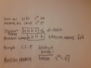
Register (fast memories that provide quick access to the values used by executing programs)
General purpose .............Eight 32-bit registers used for storing working data
Segment .....................Six 16-bit registers used for handling memory access
Instruction pointer .........A single 32-bit register pointing to the next instruction code to execute
.............................every microdevice at least must have a Program Counter (physical address)
.............................Intel and AMD use CS:IP = code segment*16, in hex add 0 at right , in binary add 0000 at right
.............................+ Instruction Pointer (EA effective address)
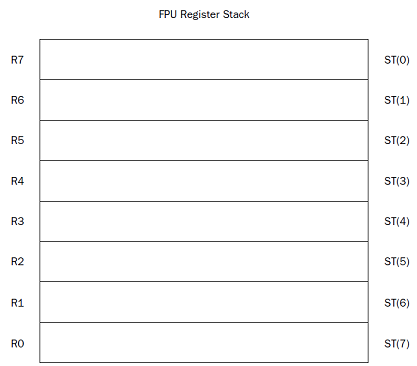
Floating-point data .........Eight 80-bit registers used for floating-point arithmetic data
Control .....................Five 32-bit registers used to determine the operating mode of the processor
Debug .......................Eight 32-bit registers used to contain information when debugging the processor
e r AX
Accumulator for operands and results data. it has a typical accumulator function. It can be used in all I / O instructions,
in string instructions and arithmetic operations. A small number of instructions requires AX.
e r BX
Pointer to data in the data memory segment, base register for address calculation, also used as internal counter, auxiliary of e r CX
e r CX
Counter for string and loop operations. it is also used as a counter in some instructions; for this reason it is indicated as count register.
e r DX
I/O pointer. it is designated as a data register. It is required by some input\output operations, as required by multiplication and division operations that, involving
great values, presuppose the pair DX, AX.
The index registers and pointers, usually contain the displacement inside the segments.
e-r-SI
Source Index. Data pointer for source of string operations. generic use index register. some string instructions require that the source string must be found
through SI
e-r-DI
Destination Index. Data pointer for destination of string operations, some instructions that handle strings, the destination must be
necessarily identified by DI.
e-r-SP
Stack pointer. it is the pointer to the top of the stack.
e-r-BP
Base Pointer, Stack data pointer, it is used as a pointer inside the stack, but it can also be used as a generic index register
31...............15.......7......0
....................High....Low...
Segment registers
The most characteristic aspect of the CPU 8086 is the segmentation of memory, Segment registers are used precisely for
keep track of the memory location of the segments in use.
The usual use is: CS identifies the segment of code (code segment) , DS the data segment, SS the stack segment and ES the extra segment.
Segment Register .............Description
CS ...........................Code segment
DS ...........................Data segment
SS ...........................Stack segment
ES ...........................Extra segment pointer
FS ...........................Extra segment pointer
GS ...........................Extra segment pointer
e r IP register (register pointing to the next instruction code to execute)
Instruction codes are always taken from the CS. About this is required a register that contains the offset of the next instruction to be performed, referenced
to the current code segment. IP contains the position of the instruction referred to the base of the code segment.

The status register (FLAGS)
The 8086 status register contains 9 1-bit indicators, also called flags. Of these, 6
they record information on the processor status (status flags) and 3 are used to check the
processor operations (control flag).
SPECIAL PURPOSE REGISTERS:
MM0 MM1 MM2 MM3 MM4 MM5 MM6 MM7
XMM0 XMM1 XMM2 XMM3 XMM4 XMM5 XMM6 XMM7
Segmentation of Memory
To transfer control of a program to a function you need to use the Stack
Stack needs an INDIRECT Addressing (it uses a Pointer to a Memory location instead directly same memory location)
Memory Addressing
The AMD64 architecture supports address relocation. To do this, several types of addresses are needed
to completely describe memory organization. Specifically, four types of addresses are defined by the
AMD64 architecture:
• Logical addresses
• Effective addresses, or segment offsets, which are a portion of the logical address.
• Linear (virtual) addresses
• Physical addresses
Logical Addresses.
A logical address is a reference into a segmented-address space. It is comprised
of the segment selector and the effective address. Notationally, a logical address is represented as
Logical Address = Segment Selector : Offset
The segment selector specifies an entry in either the global or local descriptor table. The specified
descriptor-table entry describes the segment location in virtual-address space, its size, and other
characteristics. The effective address is used as an offset into the segment specified by the selector.
Logical addresses are often referred to as far pointers. Far pointers are used in software addressing
when the segment reference must be explicit (i.e., a reference to a segment outside the current
segment).
Effective Addresses.
The offset into a memory segment is referred to as an effective address (see
“Segmentation” on page 5 for a description of segmented memory). Effective addresses are formed by
adding together elements comprising a base value, a scaled-index value, and a displacement value.
The effective-address computation is represented by the equation
Effective Address = Base + (Scale x Index) + Displacement
The elements of an effective-address computation are defined as follows:
• Base—A value stored in any general-purpose register.
• Scale—A positive value of 1, 2, 4, or 8.
• Index—A two’s-complement value stored in any general-purpose register.
• Displacement—An 8-bit, 16-bit, or 32-bit two’s-complement value encoded as part of the
instruction.
Effective addresses are often referred to as near pointers. A near pointer is used when the segment
selector is known implicitly or when the flat-memory model is used.
Long mode defines a 64-bit effective-address length. If a processor implementation does not support
the full 64-bit virtual-address space, the effective address must be in canonical form
Linear (Virtual) Addresses.
The segment-selector portion of a logical address specifies a segmentdescriptor
entry in either the global or local descriptor table. The specified segment-descriptor entry
contains the segment-base address, which is the starting location of the segment in linear-address
space. A linear address is formed by adding the segment-base address to the effective address
(segment offset), which creates a reference to any byte location within the supported linear-address
space. Linear addresses are often referred to as virtual addresses, and both terms are used
interchangeably throughout this document.
Linear Address = Segment Base Address + Effective Address
When the flat-memory model is used—as in 64-bit mode—a segment-base address is treated as 0. In
this case, the linear address is identical to the effective address. In long mode, linear addresses must be
in canonical address form
Physical Addresses.
A physical address is a reference into the physical-address space, typically
main memory. Physical addresses are translated from virtual addresses using page-translation
mechanisms. the paging mechanism is used for
virtual-address to physical-address translation. When the paging mechanism is not enabled, the virtual
(linear) address is used as the physical address.

data elements
are placed in the data section in a sequential manner, starting at the lowest memory location in
the data section, and working toward higher memory locations.
The stack behaves just the opposite. The stack is reserved at the end of the memory area, and as data is
placed on the stack, it grows downward.
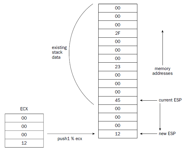
Data entry sequence: A, B, C, D, E, F, G, H
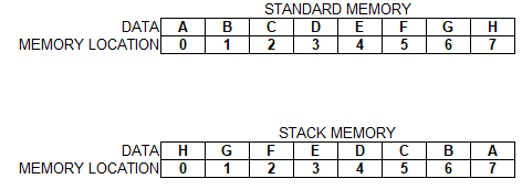
in standard memory A is placed in 0 , B is placed in 1 , C is placed in 2 and so on
in stack A is placed in 0 then B is placed in 0 and A shifts in 1, then C is placed in 0 and A shift in 2 and B shifts in 1 and so on
8 80-bit data registers R0 through R7 . fpu register is circular , the last register in the stack links back to the first register in the stack
CACHE
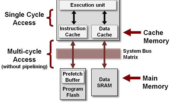
CPU cache is a separate small block of memory used to compensate for the slower access time of main memory(RAM).
A cache described as a Level 1 (L1) cache uses memory that is as fast as the CPU, so as long as the CPU is accessing the cache,
it will never have to wait for an instruction or data. Level 2 and Level 3 caches are used in conjunction with a Level 1 cache and have
memory whose access times are greater than the CPU, but are less than main memory.
CPU cache is a hardware cache used by the central processing unit (CPU) of a computer to reduce the average cost (time or energy) to
access data from the main memory (RAM).
A cache is a smaller, faster memory, located closer to a processor core. Most CPUs have different independent caches, including instruction and data caches,
where the data cache is usually organized as a hierarchy of more cache levels (L1, L2, L3, L4, etc.).
Note that the Cache is not part of Main Memory and neither Secondary storage
PAGING
In operating systems, paging is a memory management scheme by which a computer stores and retrieves data from secondary storage (as eg hd or ssd)
for use in main memory (as the ram).
by this scheme, the
operating system retrieves data from secondary storage in same-size blocks called pages.
Paging is an important part of virtual memory implementations in modern operating systems, using secondary
storage to let programs exceed the size of available physical memory.
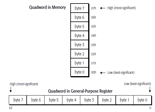
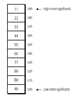
They are read from memory one byte at a time, starting with the least-significant byte (lowest
address). For example, the following instruction specifies the 64-bit instruction MOV RAX,
1122334455667788 instruction that consists of the following ten bytes:
48 B8 8877665544332211
48 is a REX instruction prefix that specifies a 64-bit operand size, B8 is the opcode that—together
with the REX prefix—specifies the 64-bit RAX destination register, and 8877665544332211 is the 8-
byte immediate value to be moved, where 88 represents the eighth (least-significant) byte and 11
represents the first (most-significant) byte. In memory, the REX prefix byte (48) would be stored at the
lowest address, and the first immediate byte (11) would be stored at the highest instruction address.
REX
An instruction encoding prefix that specifies a 64-bit operand size and provides access to
additional registers.
Zero-Extension of 32-Bit Results
when performing 32-bit operations with a
GPR (general purpose registers) destination in 64-bit mode, the processor zero-extends the 32-bit result into the full 64-bit
destination. 8-bit and 16-bit operations on GPRs preserve all unwritten upper bits of the destination
GPR. This is consistent with legacy 16-bit and 32-bit semantics for partial-width results.
Software should explicitly sign-extend the results of 8-bit, 16-bit, and 32-bit operations to the full 64-
bit width before using the results in 64-bit address calculations.
The following four code examples show how 64-bit, 32-bit, 16-bit, and 8-bit ADDs work. In these
examples, “48” is a REX prefix specifying 64-bit operand size, and “01C3” and “00C3” are the
opcode and ModRM bytes of each instruction
# in hex 1 byte = xx
Example 1: 64-bit Add:
Before:RAX =0002_0001_8000_2201
RBX =0002_0002_0123_3301
48 01C3 ADD RBX,RAX ;48 is a REX prefix for size.
Result:RBX = 0004_0003_8123_5502
Example 2: 32-bit Add:
Before:RAX = 0002_0001_8000_2201
RBX = 0002_0002_0123_3301
01C3 ADD EBX,EAX ;32-bit add
Result:RBX = 0000_0000_8123_5502
(32-bit result is zero extended)
Example 3: 16-bit Add:
Before:RAX = 0002_0001_8000_2201
RBX = 0002_0002_0123_3301
66 01C3 ADD BX,AX ;66 is 16-bit size override
Result:RBX = 0002_0002_0123_5502
(bits 63:16 are preserved)
Example 4: 8-bit Add:
Before:RAX = 0002_0001_8000_2201
RBX = 0002_0002_0123_3301
00C3 ADD BL,AL ;8-bit add
Result:RBX = 0002_0002_0123_3302
(bits 63:08 are preserved)
ARRAY
val:
.int 10, 15, 20, 25, 30, 35, 40, 45, 50, 55, 60
This creates a sequential series of data values placed in memory. Each data value occupies one unit of
memory (which in this case is a long integer, or 4 bytes). When referencing data in the array, you must
use an index system to determine which value you are accessing.
The way this is done is called indexed memory mode.
base_address(offset_address, index, size) #index must be a register
val (, %edi, 4) # note the use of the Destination Index
For example, to reference the value 20 from the values array shown, you would use the following
instructions:
movl $2, %edi
movl val(, %edi, 4), %eax
//third value is loaded in EAX
//Note that the ARRAY starts with index 0
//If any of the values are zero, they can be omitted (but the commas are still required as placeholders).
an example of Indirect addressing:
movl %edx, 4(%edi)
This instruction places the value contained in the EDX register in the memory location 4 bytes after the
location pointed to by the EDI register.
You can also go in the opposite direction:
movl %edx, -4(&edi)
This instruction places the value in the memory location 4 bytes before the location pointed to by the
EDI register.
info registers : Display the values of all registers
print ·········: Display the value of a specific register or variable from the program
print/d#dex /t #binary /x #hex
x ·············: Display the contents of a specific memory location
q: exit from gdb
h: help
l: list source lines
l line number: lines before and after that one chosen
info address var: var address
info variables: name and address of all variables
breakpoint line number : break after the line
r : exe until first break
c : restart
s : exe next instruction
until: run the program until it reaches the specified source code line
/*comments also stand on several lines*/
//comments only beginning of the line
# comments at every point
to use C library functions in assembly language program we must link the C library files
with the program object code.
On Linux systems, there
are two ways to link C functions to assembly language program.
The first method is called static
linking. Static linking links function object code directly into your application executable program file.
This creates huge executable programs, and wastes memory if multiple instances of the program are run
at the same time (each instance has its own copy of the same functions).
The second method is called dynamic linking. Dynamic linking uses libraries that enable programmers
to reference the functions in their applications,
but not link the function codes in the executable program
file.
dynamic libraries are called at the program’s runtime by the operating system, and can be
shared by multiple programs.
On Linux systems, the standard C dynamic library is located in the file
libc.so.x
where x is a value
representing the version of the library.
the library file
contains the standard C functions, including printf and exit.
we must also specify the program that will load the dynamic library at runtime.
For Linux systems, this program is
ld-linux.so.2
normally found in the /lib directory. To specify
this program, you must use the -dynamic-linker parameter of the GNU linker:
$ ld -dynamic-linker /lib/ld-linux.so.2 -o prog -lc prog.o
.section .data //another type is .rodata , any data elements defined in this section can only be accessed in read-only mode
.section .bss
.section .text
.rodata. Any data elements defined in this section can only be accessed in read-only mode
during compilation -gstabs is required before -o
gdb -q prog
break *_start //start is a label defined in .section .text
(gdb) run
label
nop
break *LABEL + Offset
break *_start+1 ######################### in MINGW is simply : break 1 , id est break+offset
run
next or step
cont
info registers
print/d /t #binary /x #hex
info variables
x/c/d/x &va //va is an example of a label defined in .section.data
c=character d=dec x=hex , size of the field, it can be b=byte h=2b w=4b
as -gstabs -o path/prog.o path/prog.s
ld -dynamic-linker /lib/ld-linux.so.2 -o path/prog -lc path/prog.o
.section .text
.globl main
main:
gcc -o path/prog path/prog.s
.section .data
label:
.directive value
example:
.section .data
msg:
.ascii “This is a test message”
factors:
.double 37.45, 45.33, 12.30
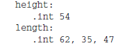
height:
.int 54
length:
.int 62, 35, 47
#The lowest memory value contains the first data element //
data elements are placed in the data section in a sequential manner, starting at the lowest memory location in
the data section, and working toward higher memory locations.
The stack behaves just the opposite. The stack is reserved at the end of the memory area, and as data is
placed on the stack, it grows downward.
.data section defines memory locations.
one label: + one or more .directive
Directive ----- Data Type
.ascii ---------Text string
.asciz ---------Null-terminated text string
.byte --------- Byte value
.double ------- 64 bit Double-precision floating-point number
.float -------- 32 bit Single-precision floating-point number
.int ---------- 32-bit integer number
.long --------- 32-bit integer number (same as .int)
.octa ----------16-byte integer number
.quad ----------8-byte integer number
.short ---------16-bit integer number
.single --------Single-precision floating-point number (same as .float)
.fill ----------fill the location with zeros
in WINDOWS using MINGW-W64
.section .text
//.globl _start /*ENTRY POINT not necessary*/
//_start: /*ENTRY POINT not necessary*/
gdb break 1
//*_start+1 not necessary
prompt dos command line to repair starting boot
bcdboot c:\Windows
ls -al /dev/sda*
brw-rw---- 1 root disk 8, 0 gen 1 18:50 /dev/sda
brw-rw---- 1 root disk 8, 1 gen 1 18:50 /dev/sda1
brw-rw---- 1 root disk 8, 2 gen 1 18:50 /dev/sda2
brw-rw---- 1 root disk 8, 3 gen 1 18:50 /dev/sda3
brw-rw---- 1 root disk 8, 4 gen 1 18:50 /dev/sda4
brw-rw---- 1 root disk 8, 5 gen 1 18:50 /dev/sda5
man 2 write
WRITE(2)
NAME
write - write to a file descriptor
SYNOPSIS
#include
ssize_t write(int fd, const void *buf, size_t count);
mov in EBX: The integer file descriptor
mov in ECX: The pointer (memory address) of the string to display
mov in EDX: The size of the string to display
sysca.s .... .o .... Xlinux
in Windows10 amd64
C:\Users\rnz>cd c:\users\rnz\onedrive\desktop
c:\Users\rnz\OneDrive\Desktop>as -gstabs -o sysca2.o sysca2.s
c:\Users\rnz\OneDrive\Desktop>ld -o sysca2.exe sysca2.o
sysca2.s .... .obj .... .exe
in Ubuntu 20.10 kernel 5.8 amd64
sysca3.s .... .o .... x
gdb -q sysca3
Reading symbols from sysca3...
(gdb) break *end
Breakpoint 1 at 0x401033: file sysca3.s, line 26.
(gdb) run
Starting program: /home/rnz/Desktop/sysca3
Breakpoint 1, end () at sysca3.s:26
26 movq $1, %rax
(gdb) x &uid
0x402008 : 0x000003e8
(gdb) x &pid
0x402000 : 0x00000952
(gdb) x &gid
0x402010 : 0x000003e8
(gdb) x/x &uid
0x402008 : 0x000003e8
(gdb) x/d &uid
0x402008 : 1000
(gdb) x/t &uid
0x402008 : 00000000000000000000001111101000
(gdb) q
A debugging session is active.
Inferior 1 [process 2386] will be killed.
Quit anyway? (y or n) y
$ id
uid=1000(rnz) gid=1000(rnz) groups=1000(rnz),4(adm),24(cdrom),27(sudo),30(dip),46(plugdev),121(lpadmin),132(lxd),133(sambashare)
$ man 2 sysinfo
sysinfo linux system call
strace program intercepts system calls made by a program and displays them
:~/Desktop/IP$ strace ./sysca3
execve("./sysca3", ["./sysca3"], 0x7fff1e175740 /* 61 vars */) = 0
strace: [ Process PID=2211 runs in 32 bit mode. ]
getpid() = 2211
getuid() = 1000
getgid() = 1000
exit(0) = ?
+++ exited with 0 +++
:~/Desktop/IP$ strace -c ./sysca3
strace: [ Process PID=2215 runs in 32 bit mode. ]
% time seconds usecs/call calls errors syscall
------ ----------- ----------- --------- --------- ----------------
0,00 0,000000 0 1 execve
------ ----------- ----------- --------- --------- ----------------
100.00 0,000000
1 total
System call usage summary for 32 bit mode:
% time seconds usecs/call calls errors syscall
------ ----------- ----------- --------- --------- ----------------
0,00 0,000000 0 1 getpid
0,00 0,000000 0 1 getuid
0,00 0,000000 0 1 getgid
------ ----------- ----------- --------- --------- ----------------
100.00 0,000000 3 total
-c Count the time, calls, and errors for each system call.
-d Show some debugging output of strace.
-e trace=call_list , Specify a filter expression for the output.
-f Trace child processes as they are created.
-ff If writing to an output file, write each child process in a separate file.
-i Print the instruction pointer at the time of the system call.
-o Write the output to the file specified.
-p Attach to the existing process by the PID specified.
-q Suppress messages about attaching and detaching.
-r Print a relative timestamp on each system call.
-t Add the time of day to each line.
-tt Add the time of day, including microseconds to each line.
-ttt Add the time of day in epoch (seconds since Jan. 1, 1970), including microseconds.
-T Show the time spent in each system call.
-v Print unabbreviated versions of the system call information (verbose).
-x Print all non-ASCII characters in hexadecimal format.
-xx Print all strings in hexadecimal format.
$ strace -o outfile id
outfile
$ strace -c id
-c id
$ strace -e trace=openat,connect,access,statfs,arch_prctl id
-e id
$ man 2 nanosleep
nanosleep
_nanosleep.s .... .o .... x (in linux)
$ ./_nanosleep &
[1] 4181 NUMBER OF THE PROCESS
$
$ ps ax | grep _nanosleep
4181 pts/0
S
0:00 ./_nanosleep
$
$ strace -p 4181 ATTACH TO RUNNING PROCESS
S_C
K
some Windows System Calls: WSC
HOME PAGE