0 0000
1 0001
2 0010
3 0011
4 0100
5 0101
6 0110
7 0111
8 1000
9 1001
a 1010
b 1011
c 1100
d 1101
e 1110
f 1111
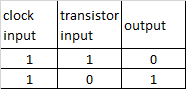
A Transistor is a switch that can be ON or OFF. an open transistor, therefore without contact between the conductors, is not crossed by electricity, provides the binary number = 0 while a closed transistor, then with contact between conductors, is traversed by current, provides the binary number = 1 The Intel pentium4 microchip has over 43,000,000 transistors, AMD athlon has at least 37,000,000.
The Oscillator, ie the Clock, adjusts the working speed of the computer, more beats = greater speed, measured in megahertz, i.e millions of beats per second.
the current passing through a transistor can be used to control another transistor. It turns the switch on ON or OFF to change the status of the second transistor. This configuration is called PORT.
the logic port NOT is composed of a single transistor that takes an Input from the Clock and an Input from another transistor. this Port produces only one output, which is always the opposite of the input coming from the transistor
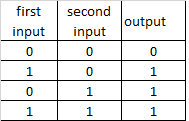
different combinations of NOT ports create other logical ports
OR
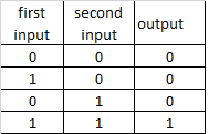
AND
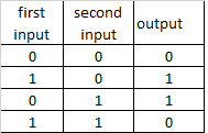
XOR
using different combinations of logical ports , the microchip executes the Addition operation from which all other mathematical operations descend.
the addition is executed through structures called Half-Adder and Full-Adder
a half-adder is made by a port XOR and a port AND which receives both the same Bit in input
eg:
2d + 3d = 10b + 11b
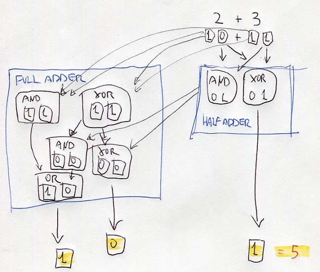
half-adder processes the digits at right using the portd XOR and AND
the resutl of XOR is the digit at right of the final result
the result of AND is the input of ports XOR and AND of the full-adder
also, the full-adder processes the digits at left of thr bits 10 and 10
the results are the inputs of other ports AND and XOR
the results are processed with the results of the half-adder
one of these results is the input of OR
all the results gives the binary number 101 that is 5 on decimal numbers
8f = 8*16^1 + f*16^0 = 143
143 = 143/16 = 8,9375 ; 0,9375*16 = 15=f ; 143d = 8f
2569 = 2569/16 = 160,56 = 160+(9) ; 160/16 = 10+(0) ; = A09h
binary number , TWO's Complement
most dignificant digit = 0 = positive
most significant digit = 1 = negative
negative bunary number = inverting bits of positive number + add 1
384 0000000110000000
-384 1111111001111111 +1 = 1111111010000000
absolute value = inverted bits of negative number + add 1
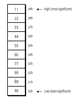
Endian refers to the position where the data begins to be processed (written, read on, transmitted/received etc) hence, the beginning of the memory address.
the definition: Endian, creates confusion!
Big Endian - Little Endian
The difference between the two systems is given by the order in which the data bytes (note: NOT BITS!!!) are stored or transmitted in memory address:
big-endian: storage / transmission starting from the most significant byte (largest end) to ending with the least significant;
little endian: storage / transmission starting from the least significant byte (smallest end) to ending with the most significant, is used on CISC machine such as Intel and AMD processors;
The big-endian order has been chosen as the standard order in many protocols used on the Internet, it is therefore also called the network byte order. It is used by ARM (advances RISC machine) processors and others Embedded (Special Purpose) microprocessors
IA-32 platform
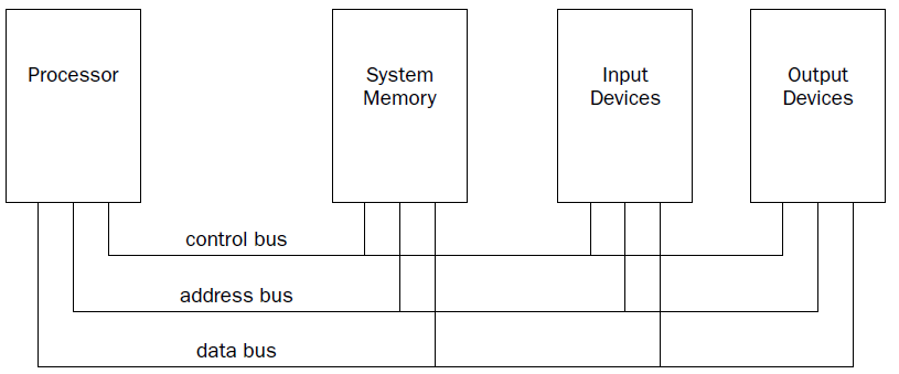
The processor contains the hardware and instruction codes that control the operation of the computer. It is connected to the other elements of the computer (the memory storage unit, input devices, and output devices) using three separate buses:
a control bus,
an address bus,
a data bus.
The control bus is used to synchronize the functions between the processor and the individual system elements. The data bus is used to move data between the processor and the external system elements. An example of this would be reading data from a memory location. The processor places the memory address to read on the address bus, and the memory storage unit responds by placing the value stored in that memory location on the data bus for the processor to access.
The processor itself consists of many components. Each component has a separate function in the processor’s ability to process data. Assembly language programs have the ability to access and control each of these elements,
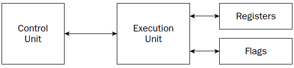
CU
At the heart of the processor is the control unit. The main purpose of the control unit is to control what is happening at any time within the processor. While the processor is running, instructions must be retrieved from memory and loaded for the processor to handle. The job of the control unit is to perform four basic functions:
1. Retrieve instructions from memory.
2. Decode instructions for operation.
3. Retrieve data from memory as needed.
4. Store the results as necessary.
The instruction counter retrieves the next instruction code from memory and prepares it to be processed. The instruction decoder is used to decode the retrieved instruction code into a micro-operation.
The MICRO-operation is the code that controls the specific signals within the processor chip to perform the function of the instruction code.
When the prepared micro-operation is ready, the control unit passes it along to the execution unit for processing, and retrieves any results to store in an appropriate location.
The NetBurst technology incorporates four separate techniques to help speed up processing in the control unit. Knowing how these techniques operate can help you optimize your assembly language programs. The NetBurst features are as follows:
❑ Instruction prefetch and decoding
❑ Branch prediction
❑ Out-of-order execution
❑ Retirement
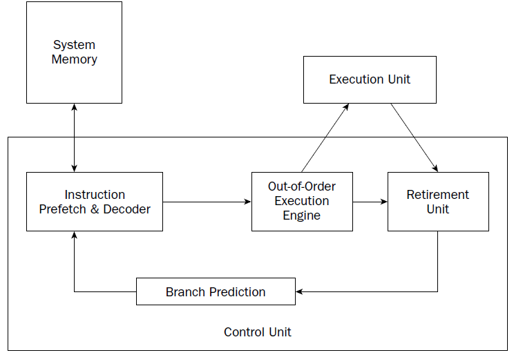
Instruction prefetch and decoding pipeline
Older processors fetched instructions and data directly from system memory as they were needed by the execution unit. Because it takes considerably longer to retrieve data from memory than to process it, a backlog occurs, whereby the processor is continually waiting for instructions and data to be retrieved from memory. To solve this problem, the concept of prefetching was created. Although the name sounds odd, prefetching involves attempting to retrieve (fetch) instructions and/or data before they are actually needed by the execution unit. To incorporate prefetching, a special storage area is needed on the processor chip itself—one that can be easily accessed by the processor, quicker than normal memory access. This was solved using pipelining.
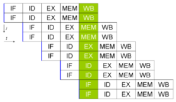 double pipeline
Pipelining involves creating a memory cache on the processor chip from which both instructions and data elements can be retrieved and stored ahead of the time that they are required for processing. When the execution unit is ready for the next instruction, that instruction is already available in the cache and can be quickly processed.
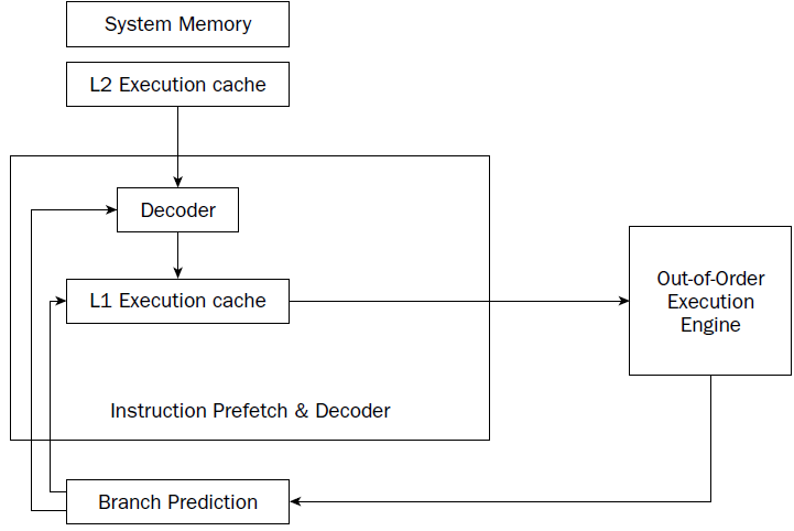
The IA-32 platform implements pipelining by utilizing two (or more) layers of cache. The first cache layer (called L1) attempts to prefetch both instruction code and data from memory as it thinks it will be needed by the processor. As the instruction pointer moves along in memory, the prefetch algorithm determines which instruction codes should be read and placed in the cache. In a similar manner, if data is being processed from memory, the prefetch algorithm attempts to determine what data elements may be accessed next and also reads them from memory and places them in cache.
there is no guarantee that the program will execute instructions in a sequential order. If the program takes a logic branch that moves the instruction pointer to a completely different location in memory, the entire cache is useless and must be cleared and repopulated with instructions from the new location.
To help alleviate this problem, a second cache layer was created. The second cache layer (called L2) can also hold instruction code and data elements, separate from the first cache layer. When the program logic jumps to a completely different area in memory to execute instructions, the second layer cache can still hold instructions from the previous instruction location. If the program logic jumps back to the area, those instructions are still being cached and can be processed almost as quickly as instructions stored in the first layer cache.
Assembly language programs cannot access the instruction and data caches.
By minimizing branches in programs, you can help speed up the execution of the instruction codes in your program.
Branch prediction unit
While implementing multiple layers of cache is one way to help speed up processing of program logic, it still does not solve the problem of “jumpy” programs. If a program takes many different logic branches, it may well be impossible for the different layers of cache to keep up, resulting in more last-minute memory access for both instruction code and data elements.
To help solve this problem, the IA-32 platform processors also incorporate branch prediction.
Branch prediction uses specialized algorithms to attempt to predict which instruction codes will be needed next within a program branch.
Special statistical algorithms and analysis are incorporated to determine the most likely path traveled through the instruction code. Instruction codes along that path are prefetched and loaded into the cache layers.
The Pentium 4 processor utilizes three techniques to implement branch prediction:
❑ Deep branch prediction
❑ Dynamic data flow analysis
❑ Speculative execution
Deep branch prediction enables the processor to attempt to decode instructions beyond multiple branches in the program. Again, statistical algorithms are implemented to predict the most likely path the program will take throughout the branches. While this technique is helpful, it is not totally foolproof.
Dynamic data flow analysis performs statistical real-time analysis of the data flow throughout the processor. Instructions that are predicted to be necessary for the flow of the program but not reached yet by the instruction pointer are passed to the out-of-order execution core . In addition, any instructions that can be executed while the processor is waiting for data related to another instruction are processed.
Speculative execution enables the processor to determine what distant instruction codes not immediately in the instruction code branch are likely to be required, and attempt to process those instructions, again using the out-of-order execution engine.
Out-of-order execution engine
The out-of-order execution engine is one of the greatest improvements to the Pentium 4 processor in terms of speed. This is where instructions are prepared for processing by the execution unit. It contains several buffers to change the order of instructions within the pipeline to increase the performance of the control unit.
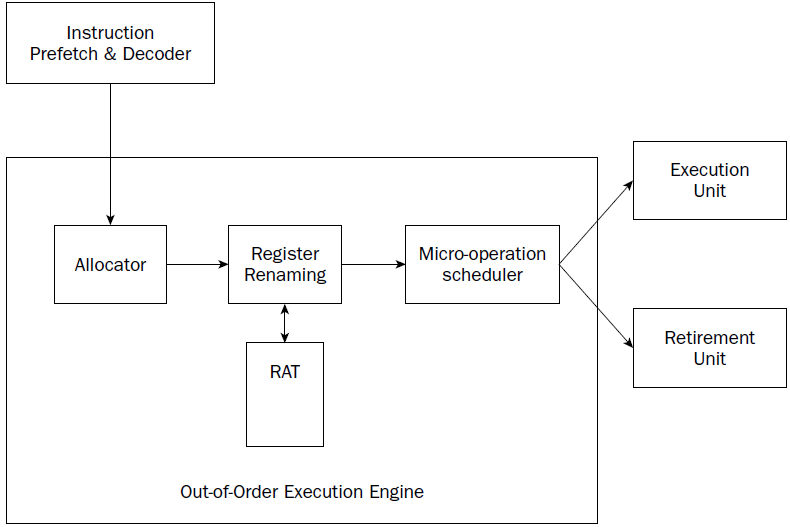
Instructions retrieved from the prefetch and decoding pipeline are analyzed and reordered, enabling them to be executed as quickly as possible. By analyzing a large number of instructions, the out-of-order execution engine can find independent instructions that can be executed (and their results saved) until required by the rest of the program. The Pentium 4 processor can have up to 126 instructions in the outof- order execution engine at any one time.
There are three sections within the out-of-order execution engine:
❑ The allocator
❑ Register renaming
❑ The micro-operation scheduler
The Allocator is the traffic cop for the out-of-order execution engine.
Its job is to ensure that buffer space is allocated properly for each instruction that the out-of-order execution engine is processing. If a needed resource is not available, the allocator will stall the processing of the instruction and allocate resources for another instruction that can complete its processing.
The register renaming section allocates logical registers to process instructions that require register access. Instead of the eight general-purpose registers available on the IA-32 processor, the register renaming section contains 128 logical registers. It maps register requests made by instructions into one of the logical registers, to allow simultaneous access to the same register by multiple instructions. The register mapping is done using the Register Allocation Table (RAT).
This helps speed up processing instructions that require access to the same register sets.
The micro-operation scheduler determines when a micro-operation is ready for processing by examining the input elements that it requires. Its job is to send micro-operations that are ready to be processed to the retirement unit, while still maintaining program dependencies.
The micro-operation scheduler uses two queues to place micro-operations, in one for micro-operations that require memory access and one for micro-operations that do not. The queues are tied to dispatch ports. Different types of Pentium processors may contain a different number of dispatch ports. The dispatch ports send the micro-operations to the retirement unit.
Retirement unit
The retirement unit receives all of the micro-operations from the pipeline decoders and the out-of-order execution engine and attempts to reassemble the micro-operations into the proper order for the program to properly execute.
The retirement unit passes micro-operations to the execution unit for processing in the order that the out-of-order execution engine sends them, but then monitors the results, reassembling the results into the proper order for the program to execute.
This is accomplished using a large buffer area to hold micro-operation results and place them in the proper order as they are required.
When a micro-operation is completed and the results placed in the proper order, the micro-operation is considered retired and is removed from the retirement unit.
The retirement unit also updates information in the branch prediction unit to ensure that it knows which branches have been taken, and which instruction codes have been processed.
Execution unit ######################################################################
Register (fast memories that provide quick access to the values used by executing programs)
General purpose .............Eight 32-bit registers used for storing working data
Segment .....................Six 16-bit registers used for handling memory access
Instruction pointer .........A single 32-bit register pointing to the next instruction code to execute
.............................every microdevice at least must have a Program Counter (physical address)
.............................Intel and AMD use CS:IP = code segment*16, in hex add 0 at right , in binary add 0000 at right
.............................+ Instruction Pointer (EA effective address)
Floating-point data .........Eight 80-bit registers used for floating-point arithmetic data
Control .....................Five 32-bit registers used to determine the operating mode of the processor
Debug .......................Eight 32-bit registers used to contain information when debugging the processor
e r AX
Accumulator for operands and results data. it has a typical accumulator function. It can be used in all I / O instructions, in string instructions and arithmetic operations. A small number of instructions requires AX.
e r BX
Pointer to data in the data memory segment, base register for address calculation, also used as internal counter, auxiliary of e r CX
e r CX
Counter for string and loop operations. it is also used as a counter in some instructions; for this reason it is indicated as count register.
e r DX
I/O pointer. it is designated as a data register. It is required by some input\output operations, as required by multiplication and division operations that, involving great values, presuppose the pair DX, AX.
The index registers and pointers, usually contain the displacement inside the segments.
e-r-SI
Source Index. Data pointer for source of string operations. generic use index register. some string instructions require that the source string must be found through SI
e-r-DI
Destination Index. Data pointer for destination of string operations, some instructions that handle strings, the destination must be necessarily identified by DI.
e-r-SP
Stack pointer. it is the pointer to the top of the stack.
e-r-BP
Base Pointer, Stack data pointer, it is used as a pointer inside the stack, but it can also be used as a generic index register
31...............15.......7......0
....................High....Low...
Segment registers
The most characteristic aspect of the CPU 8086 is the segmentation of memory, Segment registers are used precisely for keep track of the memory location of the segments in use.
The usual use is: CS identifies the segment of code (code segment) , DS the data segment, SS the stack segment and ES the extra segment.
e r IP register (register pointing to the next instruction code to execute)
Instruction codes are always taken from the CS. About this is required a register that contains the offset of the next instruction to be performed, referenced to the current code segment. IP contains the position of the instruction referred to the base of the code segment.

The status register (FLAGS)
The 8086 status register contains 9 1-bit indicators, also called flags. Of these, 6 they record information on the processor status (status flags) and 3 are used to check the processor operations (control flag).
SPECIAL PURPOSE REGISTERS:
MM0 MM1 MM2 MM3 MM4 MM5 MM6 MM7
XMM0 XMM1 XMM2 XMM3 XMM4 XMM5 XMM6 XMM7
Memory Addressing
The AMD64 architecture supports address relocation. To do this, several types of addresses are needed to completely describe memory organization. Specifically, four types of addresses are defined by the
AMD64 architecture:
• Logical addresses
• Effective addresses, or segment offsets, which are a portion of the logical address.
• Linear (virtual) addresses
• Physical addresses
Logical Addresses.
A logical address is a reference into a segmented-address space. It is comprised of the segment selector and the effective address. Notationally, a logical address is represented as
Logical Address = Segment Selector : Offset
The segment selector specifies an entry in either the global or local descriptor table. The specified descriptor-table entry describes the segment location in virtual-address space, its size, and other characteristics. The effective address is used as an offset into the segment specified by the selector. Logical addresses are often referred to as far pointers. Far pointers are used in software addressing when the segment reference must be explicit (i.e., a reference to a segment outside the current segment).
Effective Addresses.
The offset into a memory segment is referred to as an effective address (see “Segmentation” on page 5 for a description of segmented memory). Effective addresses are formed by adding together elements comprising a base value, a scaled-index value, and a displacement value.
The effective-address computation is represented by the equation
Effective Address = Base + (Scale x Index) + Displacement
The elements of an effective-address computation are defined as follows:
• Base—A value stored in any general-purpose register.
• Scale—A positive value of 1, 2, 4, or 8.
• Index—A two’s-complement value stored in any general-purpose register.
• Displacement—An 8-bit, 16-bit, or 32-bit two’s-complement value encoded as part of the instruction.
Effective addresses are often referred to as near pointers. A near pointer is used when the segment selector is known implicitly or when the flat-memory model is used.
Long mode defines a 64-bit effective-address length. If a processor implementation does not support the full 64-bit virtual-address space, the effective address must be in canonical form
Linear (Virtual) Addresses.
The segment-selector portion of a logical address specifies a segmentdescriptor entry in either the global or local descriptor table. The specified segment-descriptor entry contains the segment-base address, which is the starting location of the segment in linear-address space. A linear address is formed by adding the segment-base address to the effective address (segment offset), which creates a reference to any byte location within the supported linear-address space. Linear addresses are often referred to as virtual addresses, and both terms are used interchangeably throughout this document.
Linear Address = Segment Base Address + Effective Address
When the flat-memory model is used—as in 64-bit mode—a segment-base address is treated as 0. In this case, the linear address is identical to the effective address. In long mode, linear addresses must be in canonical address form
Physical Addresses.
A physical address is a reference into the physical-address space, typically main memory. Physical addresses are translated from virtual addresses using page-translation mechanisms. the paging mechanism is used for virtual-address to physical-address translation. When the paging mechanism is not enabled, the virtual (linear) address is used as the physical address.
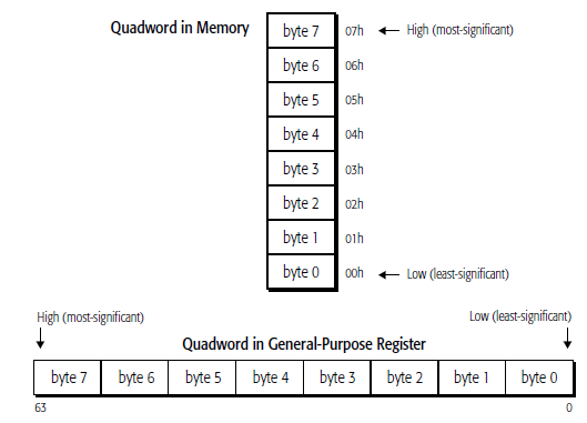
They are read from memory one byte at a time, starting with the least-significant byte (lowest address). For example, the following instruction specifies the 64-bit instruction MOV RAX, 1122334455667788 instruction that consists of the following ten bytes:
48 B8 8877665544332211
48 is a REX instruction prefix that specifies a 64-bit operand size, B8 is the opcode that—together with the REX prefix—specifies the 64-bit RAX destination register, and 8877665544332211 is the 8- byte immediate value to be moved, where 88 represents the eighth (least-significant) byte and 11 represents the first (most-significant) byte. In memory, the REX prefix byte (48) would be stored at the lowest address, and the first immediate byte (11) would be stored at the highest instruction address.
REX
An instruction encoding prefix that specifies a 64-bit operand size and provides access to additional registers.
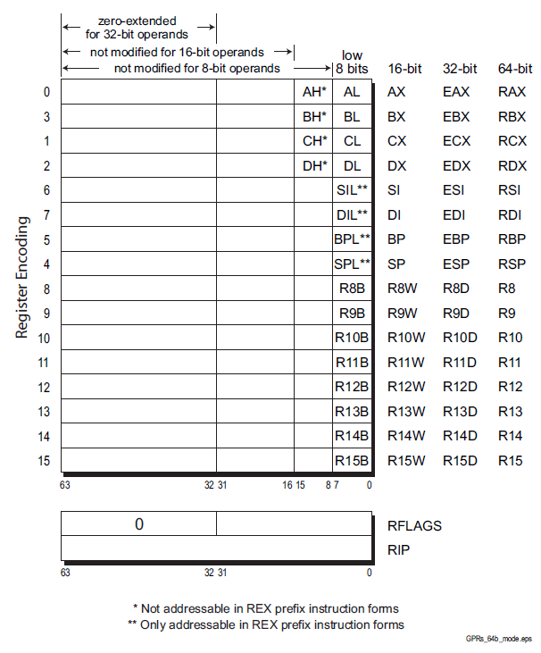
Zero-Extension of 32-Bit Results when performing 32-bit operations with a GPR (general purpose registers) destination in 64-bit mode, the processor zero-extends the 32-bit result into the full 64-bit destination. 8-bit and 16-bit operations on GPRs preserve all unwritten upper bits of the destination GPR. This is consistent with legacy 16-bit and 32-bit semantics for partial-width results. Software should explicitly sign-extend the results of 8-bit, 16-bit, and 32-bit operations to the full 64- bit width before using the results in 64-bit address calculations. The following four code examples show how 64-bit, 32-bit, 16-bit, and 8-bit ADDs work. In these examples, “48” is a REX prefix specifying 64-bit operand size, and “01C3” and “00C3” are the opcode and ModRM bytes of each instruction
# in hex 1 byte = xx
Example 1: 64-bit Add:
Before:RAX =0002_0001_8000_2201
RBX =0002_0002_0123_3301
48 01C3 ADD RBX,RAX ;48 is a REX prefix for size.
Result:RBX = 0004_0003_8123_5502
Example 2: 32-bit Add:
Before:RAX = 0002_0001_8000_2201
RBX = 0002_0002_0123_3301
01C3 ADD EBX,EAX ;32-bit add
Result:RBX = 0000_0000_8123_5502
(32-bit result is zero extended)
Example 3: 16-bit Add:
Before:RAX = 0002_0001_8000_2201
RBX = 0002_0002_0123_3301
66 01C3 ADD BX,AX ;66 is 16-bit size override
Result:RBX = 0002_0002_0123_5502
(bits 63:16 are preserved)
Example 4: 8-bit Add:
Before:RAX = 0002_0001_8000_2201
RBX = 0002_0002_0123_3301
00C3 ADD BL,AL ;8-bit add
Result:RBX = 0002_0002_0123_3302
(bits 63:08 are preserved)
Segment Register .............Description
CS ...........................Code segment
DS ...........................Data segment
SS ...........................Stack segment
ES ...........................Extra segment pointer
FS ...........................Extra segment pointer
GS ...........................Extra segment pointer
CACHE
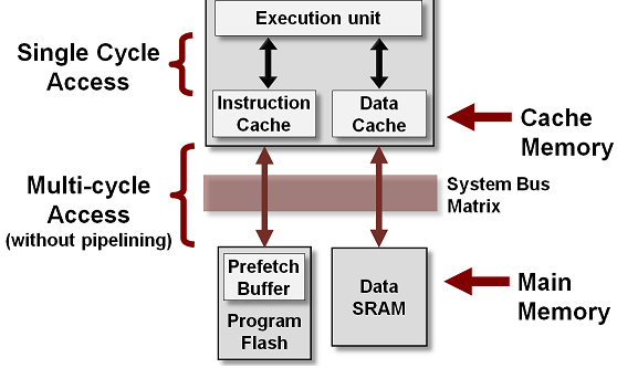
CPU cache is a separate small block of memory used to compensate for the slower access time of main memory(RAM).
A cache described as a Level 1 (L1) cache uses memory that is as fast as the CPU, so as long as the CPU is accessing the cache, it will never have to wait for an instruction or data. Level 2 and Level 3 caches are used in conjunction with a Level 1 cache and have memory whose access times are greater than the CPU, but are less than main memory.
CPU cache is a hardware cache used by the central processing unit (CPU) of a computer to reduce the average cost (time or energy) to access data from the main memory (RAM).
A cache is a smaller, faster memory, located closer to a processor core. Most CPUs have different independent caches, including instruction and data caches, where the data cache is usually organized as a hierarchy of more cache levels (L1, L2, L3, L4, etc.).
Driver:
code to control a specific device. Bios extension. It prevents the Bios ,that resides in a permanent memory, from having to include all the commands for each hardware component, to avoid to assume enormous dimensions and to become quickly obsolete.
ARRAY
val:
.int 10, 15, 20, 25, 30, 35, 40, 45, 50, 55, 60
This creates a sequential series of data values placed in memory. Each data value occupies one unit of memory (which in this case is a long integer, or 4 bytes). When referencing data in the array, you must use an index system to determine which value you are accessing. The way this is done is called indexed memory mode.
base_address(offset_address, index, size) #index must be a register
val (, %edi, 4) # note the use of the Destination Index
For example, to reference the value 20 from the values array shown, you would use the following instructions:
movl $2, %edi
movl val(, %edi, 4), %eax
//third value is loaded in EAX
//Note that the ARRAY starts with index 0
//If any of the values are zero, they can be omitted (but the commas are still required as placeholders).
an example of Indirect addressing:
movl %edx, 4(%edi)
This instruction places the value contained in the EDX register in the memory location 4 bytes after the location pointed to by the EDI register.
You can also go in the opposite direction:
movl %edx, -4(&edi)
This instruction places the value in the memory location 4 bytes before the location pointed to by the EDI register.
info registers : Display the values of all registers
print ·········: Display the value of a specific register or variable from the program
print/d#dex /t #binary /x #hex
x ·············: Display the contents of a specific memory location
q: exit from gdb
h: help
l: list source lines
l line number: lines before and after that one chosen
info address var: var address
info variables: name and address of all variables
breakpoint line number : break after the line
r : exe until first break
c : restart
s : exe next instruction
until: run the program until it reaches the specified source code line
/*comments also stand on several lines*/
//comments only beginning of the line
# comments at every point
to use C library functions in assembly language program we must link the C library files with the program object code.
On Linux systems, there are two ways to link C functions to assembly language program.
The first method is called static linking. Static linking links function object code directly into your application executable program file. This creates huge executable programs, and wastes memory if multiple instances of the program are run at the same time (each instance has its own copy of the same functions).
The second method is called dynamic linking. Dynamic linking uses libraries that enable programmers to reference the functions in their applications,
but not link the function codes in the executable program file.
dynamic libraries are called at the program’s runtime by the operating system, and can be shared by multiple programs.
On Linux systems, the standard C dynamic library is located in the file
libc.so.x
where x is a value representing the version of the library.
the library file contains the standard C functions, including printf and exit.
we must also specify the program that will load the dynamic library at runtime.
For Linux systems, this program is
ld-linux.so.2
normally found in the /lib directory. To specify this program, you must use the -dynamic-linker parameter of the GNU linker:
$ ld -dynamic-linker /lib/ld-linux.so.2 -o prog -lc prog.o
.section .data //another type is .rodata , any data elements defined in this section can only be accessed in read-only mode
.section .bss
.section .text
.rodata. Any data elements defined in this section can only be accessed in read-only mode
during compilation -gstabs is required
gdb -q prog
break *_start //start is a label defined in .section .text
(gdb) run
label
nop
break *LABEL + Offset
break *_start+1 ######################### in MINGW is simply : break 1 , id est break+offset
run
next or step
cont
info registers
print/d /t #binary /x #hex
info variables
x/c/d/x &va //va is an example of a label defined in .section.data
c=character d=dec x=hex , size of the field, it can be b=byte h=2b w=4b
as -gstabs -o path/prog.o path/prog.s
ld -dynamic-linker /lib/ld-linux.so.2 -o path/prog -lc path/prog.o
.section .text
.globl main
main:
gcc -o path/prog path/prog.s
.section .data
label:
.directive value
example:
.section .data
msg:
.ascii “This is a test message”
factors:
.double 37.45, 45.33, 12.30
height:
.int 54
length:
.int 62, 35, 47
#The lowest memory value contains the first data element // data elements are placed in the data section in a sequential manner, starting at the lowest memory location in the data section, and working toward higher memory locations. The stack behaves just the opposite. The stack is reserved at the end of the memory area, and as data is placed on the stack, it grows downward.
.data section defines memory locations.
one label: + one or more .directive
Directive ----- Data Type
.ascii ---------Text string
.asciz ---------Null-terminated text string
.byte --------- Byte value
.double ------- 64 bit Double-precision floating-point number
.float -------- 32 bit Single-precision floating-point number
.int ---------- 32-bit integer number
.long --------- 32-bit integer number (same as .int)
.octa ----------16-byte integer number
.quad ----------8-byte integer number
.short ---------16-bit integer number
.single --------Single-precision floating-point number (same as .float)
.fill ----------fill the location with zeros
#pp
.section .data
va:
.long 45
.float 3.4
.byte 4, 9, 21
.ascii "shits"
.section .text
.globl _start
_start: nop
movl va, %ecx //MOVE VA VALUE IN REGISTER ECX
movl $1, %eax //standard
movl $0, %ebx //standard
int $0x80 //standard linux //in dos = $0x20
to verify the value stored in the memory location was moved to the ECX register:
GDB -q prog
break *_start+1
run
print\x $register
next
print\x $register
The .equ directive is used to set a constant value to a symbol that can be used in the text section, as shown in the following examples:
.equ factor, 3
.equ LINUX_SYS_CALL, 0x80
To reference the static data element, you must use a dollar sign before the constant declared
The bss section
Defining data elements in the bss section is somewhat different from defining them in the data section. Instead of declaring specific data types, you just declare raw segments of memory that are reserved for whatever purpose you need them for. The GNU assembler uses two directives to declare buffers, as shown following
Directive
.comm //Declares a common memory area for data that is not initialized .lcomm //Declares a local common memory area for data that is not initialized
While the two sections work similarly, the local common memory area is reserved for data that will not be accessed outside of the local assembly code. The format for both of these directives is
.comm symbol, length
where symbol is a label assigned to the memory area, and length is the number of bytes contained in the memory area, as shown in the following example:
.section .bss
.lcomm buffer, 10000
These statements assign a 10,000-byte memory area to the buffer label. Local common memory areas cannot be accessed by functions outside of where they were declared (they can’t be used in .globl directives).
One benefit to declaring data in the bss section is that the data is not included in the executable program. When data is defined in the data section, it must be included in the executable program, since it must be initialized with a specific value. Because the data areas declared in the bss section are not initialized with program data, the memory areas are reserved at runtime, and do not have to be included in the final program
To wiew the size of the program:
as -o prog.o prog.s
ld -o prog prog.o
ls -al prog //generates the output that shows the number of bytes
.section .bss
.lcomm buffer, 10000 //directive of .bss
.section .text
.globl _start
_start:
movl $1, %eax
movl $0, %ebx
int $0x80
10000 bytes reserved are not increased in the size of the executable program file
instead
.section .data
buffer:
.fill 10000 //directive of .data
.section .text
.globl _start
_start:
movl $1, %eax
movl $0, %ebx
int $0x80
now the size of the executable program file is increased of 10000 bytes. The default is to create one byte per field, and fill it with zeros. instead the directive .bytes declares a value
movl %eax, %ebx
movw %ax, %bx
movb %al, %bl
An immediate data element to a general-purpose register
An immediate data element to a memory location
A general-purpose register to another general-purpose register
A general-purpose register to a segment register
A segment register to a general-purpose register
A general-purpose register to a control register
A control register to a general-purpose register
A general-purpose register to a debug register
A debug register to a general-purpose register
A memory location to a general-purpose register
A memory location to a segment register
A general-purpose register to a memory location
A segment register to a memory location
//rtm
.section .data
ml:
.long 545
.section .text
.globl _start
_start:
nop
movl $444, %eax
movl %eax, ml #the previous of ml value is deleted and replaced
movl $1, %eax
movl $0, %ebx
int $0x80
$ gdb -q rtm
(gdb) break *_start+1
Breakpoint 1 at 0x8048075: file rtm.s line 9.
(gdb) run
Starting program: /...........
Breakpoint 1, _start () at rtm...
9 movl $444, %eax
(gdb) x/d &ml
0x804908b: 545
(gdb) s # net instruction
12 movl %eax, ml
(gdb) s
13 movl $1, %eax
(gdb) x/d &ml
0x804908b: 444
(gdb) x/t &ml
0x804908b: 000000000000000000000110111100
(gdb) x/x &ml
0x804908b: 0x000001bc
(gdb)
(gdb) x/4d &values
0x402000
(gdb) x/4x &values
0x402000
(gdb) x/4t &values
0x402000
$ ./i.a
$ echo $?
100
CF Carry flag A mathematical expression has created a carry or borrow
OF Overflow flag An integer value is either too large or too small
PF Parity flag The register contains corrupt data from a mathematical operation
SF Sign flag Indicates whether the result is negative or positive
ZF Zero flag The result of the mathematical operation is zero
Instruction Pair .......Description ..............EFLAGS Condition
CMOVA/CMOVNBE ......Above/not below or equal .....(CF or ZF) = 0
CMOVAE/CMOVNB ......Above or equal/not below .....CF=0
CMOVNC .............Not carry ....................CF=0
CMOVB/CMOVNAE ......Below/not above or equal .....CF=1
CMOVC ..............Carry ........................CF=1
CMOVBE/CMOVNA ......Below or equal/not above .....(CF or ZF) = 1
CMOVE/CMOVZ ........Equal/zero ...................ZF=1
CMOVNE/CMOVNZ ......Not equal/not zero ...........ZF=0
CMOVP/CMOVPE .......Parity/parity even ...........PF=1
CMOVNP/CMOVPO ......Not parity/parity odd ........PF=0
CMOVGE/CMOVNL ......Greater or equal/not less ....(SF xor OF)=0
CMOVL/CMOVNGE ......Less/not greater or equal ....(SF xor OF)=1
CMOVLE/CMOVNG ......Less or equal/not greater ....((SF xor OF) or ZF)=1
CMOVO ..............Overflow .....................OF=1
CMOVNO .............Not overflow .................OF=0
CMOVS ..............Sign (negative) ..............SF=1
CMOVNS .............Not sign (non-negative) ......SF=0
# cmv
.section .data
output:
.asciz “The largest value is %d\n”
va:
.int 105, 235, 61, 315, 134, 221, 53, 145, 117, 5
.section .text
.globl _start
_start:
nop
movl va, %ebx
movl $1, %edi
loop:
movl va(, %edi, 4), %eax
cmp %ebx, %eax
cmova %eax, %ebx
inc %edi
cmp $10, %edi
jne loop
pushl %ebx
pushl $output
call printf
addl $8, %esp
pushl $0
call exit
(gdb) s
14 movl va(, %edi, 4), %eax
(gdb) s
15 cmp %ebx, %eax
(gdb) print $eax
$1 = 235
(gdb) print $ebx
$2 = 105
(gdb) s
16 cmova %eax, %ebx
(gdb) s
17 inc %edi
(gdb) print $ebx
$3 = 235
$ ./cmv
The largest value is 315
exchange of values:
MOVW %AX , %CX # TMP , cx spare register
MOVW %BX , %AX
MOVW %CX , %AX
The BSWAP instruction reverses the order of the bytes in a register.
It is important to remember that the bits are not reversed; but rather, the individual bytes contained within the register are reversed. This produces a big-endian value from a little-endian value, and visa versa.
movl $0x12345678, %ebx #######
Current language: auto; currently asm
(gdb) step
_start () at swaptest.s:
bswap %ebx ######## (gdb) print/x $ebx
$1 = 0x12345678
(gdb) step
_start () at swaptest.s:7
7 movl $1, %eax ######## after this instruction the bytes result reversed
(gdb) print/x $ebx
$2 = 0x78563412 ############ 4 bytes reversed
XADD
The XADD instruction is used to exchange the values between two registers, or a memory location and a register, add the values, and then store them in the destination location (either a register or a memory location). The format of the XADD instruction is
xadd source, destination
where source must be a register, and destination can be either a register or a memory location, and contains the results of the addition. The registers can be 8-, 16-, or 32-bit register values.
CMPXCHG
The CMPXCHG instruction compares the destination operand with the value in the EAX, AX, or AL registers. If the values are equal, the value of the source operand value is loaded into the destination operand. If the values are not equal, the destination operand value is loaded into the EAX, AX, or AL registers. The CMPXCHG instruction is not available on processors earlier than the 80486. In the GNU assembler, the format of the CMPXCHG instruction is
cmpxchg source, destination
which is the reverse of the Intel documents. The destination operand can be an 8-, 16-, or 32-bit register, or a memory location. The source operand must be a register whose size matches the destination operand.
# prog
.section .data
data:
.int 10
.section .text
.globl _start
_start:
nop
movl $10, %eax
movl $5, %ebx
cmpxchg %ebx, data
movl $1, %eax
int $0x80
The memory location referenced by the data label is compared with the value in the EAX register using the CMPXCHG instruction. Because they are equal, the value in the source operand (EBX) is loaded in the data memory location, and the value in the EBX register remains the same. You can check this behavior using the debugger:
(gdb) run
9 movl $10, %eax
(gdb) step
10 movl $5, %ebx
(gdb) step
11 cmpxchg %ebx, data
(gdb) x/d &data
0x8049090 : 10
(gdb) s
12 movl $1, %eax
(gdb) print $eax $3 = 10
(gdb) print $ebx
$4 = 5 (gdb) x/d &data
0x8049090 : 5
(gdb)
Before the CMPXCHG instruction, the value of the data memory location is 10, which matches the value set in the EAX register. After the CMPXCHG instruction, the value in EBX (which is 5) is moved to the data memory location.
Because that value does not match the value in EAX, you will notice that the data value is not changed, but the EAX value now contains the value you set in the data label.
//8
.section .data
dat:
.byte 0x88, 0x77 , 0x66, 0x55, 0x44, 0x33, 0x22, 0x11
.section .text
.globl _start
_start:
nop
movl $0x88776655 , %edx #32 bit
movl $0x44332211 , %eax
movl $0x22222222 , %ecx
movl $0x11111111 , %ebx
cmpxchg8b dat
movl $0 , %ebx
movl $1 , %eax
int $0x80
(gdb) x/2x &dat
0x402000
//88 .section .data
dat:
.byte 0x11, 0x22 , 0x33, 0x44, 0x55, 0x66, 0x77, 0x88
.section .text
.globl _start
_start:
nop
movl $0x88776655 , %edx
movl $0x44332211 , %eax
movl $0x22222222 , %ecx
movl $0x11111111 , %ebx
cmpxchg8b dat
movl $0 , %ebx
movl $1 , %eax
int $0x80
(gdb) x/2x &dat
0x402000
movl $va, %edi
This instruction moves the memory address of the label VA to the EDI register.
The dollar sign ($) before the label name instructs the assembler to use the memory address, and not the data value located at the address.
next instruction:
movl %ebx, (%edi)
is the other half of the indirect addressing mode.
Without the parentheses around the EDI register, the instruction would just load the value in the EBX register to the EDI register. With the parentheses around the EDI register, the instruction instead moves the value in the EBX register to the memory location, the label VA, contained in the EDI register.
This is a very powerful tool. Similar to pointers in C and C++, it enables you to control memory address locations with a register. The real power is realized by incrementing the indirect addressing value contained in the register.
movl %edx, 4(%edi)
This instruction places the value contained in the EDX register in the memory location 4 bytes after the location pointed to by the EDI register. You can also go in the opposite direction:
movl %edx, -4(&edi)
This instruction places the value in the memory location 4 bytes before the location pointed to by the EDI register.
HOW THE MACHINE ARRANGES THE BYTES:
dat:
.byte 0x88, 0x77 , 0x66, 0x55, 0x44, 0x33, 0x22, 0x11
generates &dat = 0x55667788 0x11223344 #2*32 bit
dat:
.byte 0x11, 0x22 , 0x33, 0x44, 0x55, 0x66, 0x77, 0x88
generates &dat = 0x88776655 0x44332211
if ECX:EBX registers were placed in the data memory location :
&dat = ebx:ecx
Breakpoint 1, _start () at 8.s:9
9 movl $0x88776655 , %edx
(gdb) s
10 movl $0x44332211 , %eax
(gdb) s
11 movl $0x22222222 , %ecx
(gdb) s
12 movl $0x11111111 , %ebx
(gdb) s
13 cmpxchg8b dat
(gdb) x/2x &dat
0x804909c: 0x55667788 0x11223344
(gdb) x/2x &eax
No symbol "eax" in current context.
(gdb) x/2x $eax
0x44332211: Cannot access memory at address 0x44332211
(gdb) print $eax
$1 = 1144201745
(gdb) print/x $eax
$2 = 0x44332211
(gdb) print/x $edx
$3 = 0x88776655
(gdb) info registers
eax 0x44332211 1144201745
ecx 0x22222222 572662306
edx 0x88776655 -2005440939
ebx 0x11111111 286331153
esp 0xbffff2b0 0xbffff2b0
ebp 0x0 0x0
esi 0x0 0
edi 0x0 0
eip 0x8048089 0x8048089 <_start+21>
eflags 0x202 [ IF ]
cs 0x73 115
ss 0x7b 123
ds 0x7b 123
es 0x7b 123
fs 0x0 0
gs 0x0 0
(gdb) Quit
(gdb) Quit
(gdb)
then checked and verified that the Label dat is not equal to edx:eax , cmpxchg8b moves the values stored in DAT in edx:eax ordening as 0x88776655:0x44332211
Verifying this by
DAT:
.byte 0x77, 0x55, 0x22, 0x23, 0x32, 0x98, 0x11, 0x45
#8b8
.section .data
DAT:
.byte 0x77, 0x55, 0x22, 0x23, 0x32, 0x98, 0x11, 0x45
.section .text
.globl _start
_start:
nop
movl $0x88776655, %edx
movl $0x44332211, % eax
movl $0x22222222, %ecx
movl $0x11111111, %ebx
cmpxchg8b DAT
movl $0x0 , %ebx
movl $0x1, %eax
int $0x080
(gdb) x/2x &DAT
0x402000 <_data_start__>: 0x23225577 0x45119832
//why not 0x45119832 0x23225577 ? why are the 2 groups of 32 bits sorted like this? which the key?
(gdb) info registers
eax 0x23225577 589452663
ecx 0x22222222 572662306
edx 0x45119832 1158780978
ebx 0x11111111 286331153
The basic algorithm for a sort in the high-level language "c" is:
for(out = array_size-1; out>0, out--)
{
for(in = 0; in < out; in++)
{
if (array[in] > array[in+1])
swap(array[in], array[in+1]);
}
}
There are two loops. The inner loop runs through the array, checking the adjacent array value to see which is larger. If a larger value is found in front of a smaller value, the two values are swapped in the array. This continues through to the end of the array.
When the first pass has completed, the largest value in the array should be at the end of the array, but the remaining values are not in any particular order. You must take N-1 passes through an array of N elements before all of the elements are in sorted order. The outer loop controls how many total passes of the inner loop are performed. For each new pass of the inner loop, there is one less element to check, as the last element of the previous pass should be in the proper order.
This algorithm is implemented in the assembly language program using a data array and two counters, EBX and ECX. The EBX counter is used for the inner loop, decreasing each time an array element is tested. When it reaches zero, the ECX counter is decreased, and the EBX counter is reset. This process continues until the ECX counter reaches zero. This indicates that all of the required passes have been completed.
algorithm to sort an array of integers, not the most efficient sort method, but it is the easiest to understand and demonstrate.
# sort
.section .data
va:
.int 105, 235, 61, 315, 134, 221, 53, 145, 117, 5
.section .text
.globl _start
_start:
movl $va, %esi
movl $9, %ecx # 9 comparisons
movl $9, %ebx
loop:
movl (%esi), %eax
cmp %eax, 4(%esi)
jge skip
xchg %eax, 4(%esi)
movl %eax, (%esi)
skip:
add $4, %esi
dec %ebx
jnz loop
// after ebx reaches 0, then ecx decrease to 8, then after ebx = 0 again, ecx decrease to 7 and so on to zero
dec %ecx /*decreasee only ebx loop ended*/
jz end
movl $va, %esi
movl %ecx, %ebx /* now ebx is resetted to 8, then after a new loop is resetted to 7,..,6.....,1 */
jmp loop
end:
movl $1, %eax
movl $0, %ebx
int $0x80
The actual comparing and swapping of array values is done using indirect addressing. The ESI register is loaded with the memory address of the start of the data array. The ESI register is then used as a pointer to each array element during the comparison section:
movl (%esi), %eax
cmp %eax, 4(%esi)
jge skip
xchg %eax, 4(%esi)
movl %eax, (%esi)
skip:
First, the value in the first array element is loaded into the EAX register, and compared with the second array element (located 4 bytes from the first). If the second element is already larger than or equal to the first element, nothing happens and the program moves on to the next pair.
If the second element is less than the first element, the XCHG instruction is used to swap the first element (loaded into the EAX register) with the second element in memory. Next, the second element (now loaded into the EAX register) is then placed in the first element location in memory.
After this, the ESI register is incremented by 4 bytes, now pointing to the second element in the array. The process is then repeated, now using the second and third array elements. This continues until the end of the array is reached.
This simple sample program does not produce any output. Instead, to see if it really works, you can use the debugger and view the values array before and after the program is run. Here’s a sample output of the program in action:
C:\>gdb -q users\\rnz\desktop\sort.exe
Reading symbols from users\\rnz\desktop\sort.exe...done.
(gdb) break *end
Breakpoint 1 at 0x40102d: file users\rnz\desktop\sort.s, line 27.
(gdb) x/10d &values
0x402000
0x402010
0x402020
(gdb) run
Starting program: C:\users\rnz\desktop\sort.exe
[New Thread 14156.0x2b00]
Breakpoint 1, end () at users\rnz\desktop\sort.s:27
27 movl $1, %eax
(gdb) x/10d &values
0x402000
0x402010
0x402020
(gdb)
# sort.exp
.section .data
va:
.int 105, 235, 61, 315, 134, 221, 53, 145, 117, 5
.section .text
.globl _start
_start:
movl $va, %esi
movl $9, %ecx
movl $9, %ebx
loop:
movl (%esi), %eax
cmp %eax, 4(%esi)
jge skip
xchg %eax, 4(%esi)
movl %eax, (%esi)
skip:
add $4, %esi
dec %ebx
jnz loop
dec %ecx
jz end
movl $va, %esi
//movl %ecx, %ebx ############### NOTICE!!!
jmp loop
end:
movl $1, %eax
movl $0, %ebx
int $0x80
C:\>as -gstabs -o users\rnz\desktop\sort.exp.o users\rnz\desktop\sort.exp.s
C:\>ld -o users\rnz\desktop\sort.exp.exe users\rnz\desktop\sort.exp.o
C:\>gdb -q users\rnz\desktop\sort.exp.exe
Reading symbols from users\rnz\desktop\sort.exp.exe...done.
(gdb) break *end
Breakpoint 1 at 0x40102b: file users\rnz\desktop\sort.exp.s, line 27.
(gdb) x/10d &va
0x402000
0x402010
0x402020
(gdb) run
Starting program: C:\users\rnz\desktop\sort.exp.exe
[New Thread 10920.0x2b28]
Program received signal SIGSEGV, Segmentation fault.
loop () at users\rnz\desktop\sort.exp.s:15
15 xchg %eax, 4(%esi)
(gdb) x/10d &va
0x402000
0x402010
0x402020
(gdb)
##############FAILED SORT!!!!!!!!!!!!!!!!!!!!!!!!
the Stack reverse the order of data insertion/retrieving, id est begin fron higher address to lower address.
Stack it's a LIFO system with stack pointer to its top
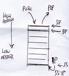
pushx source
pushl %ecx # puts the 32-bit value of the ECX register on the stack
pushw %cx # puts the 16-bit value of the CX register on the stack
pushl $100 # puts the value of 100 on the stack as a 32-bit integer value
pushl data # puts the 32-bit data value referenced by the data label
pushl $data # puts the 32-bit memory address referenced by the data label
Note the difference between using the label data versus the memory location $data.
The first format (without the dollar sign) places the data value contained in the memory location in the stack,
whereas the second format places the memory address referenced by the label in the stack.
popx destination
popl %ecx # place the next 32-bits in the stack in the ECX register
popw %cx # place the next 16-bits in the stack in the CX register
popl value # place the next 32-bits in the stack in the value memory location
Instruction Description
PUSHA/POPA Push or pop all of the 16-bit general-purpose registers
PUSHAD/POPAD Push or pop all of the 32-bit general-purpose registers
PUSHF/POPF Push or pop the lower 16 bits of the EFLAGS register
PUSHFD/POPFD Push or pop the entire 32 bits of the EFLAGS register
The PUSHA and POPA instructions are great for quickly setting aside and retrieving the current state of all the general-purpose registers at once. The PUSHA instruction pushes the 16-bit registers so they appear on the stack in the following order: DI, SI, BP, BX, DX, CX, and finally, AX. The PUSHAD instruction pushes the 32-bit counterparts of these registers in the same order. The POPA and POPAD instructions retrieve the registers in the reverse order they were pushed.
The behavior of the POPF and POPFD instructions varies depending on the processor mode of operation. When the processor is running in protected mode in ring 0 (the privileged mode), all of the nonreserved flags in the EFLAGS register can be modified, with the exception of the VIP, VIF, and VM flags. The VIP and VIF flags are cleared, and the VM flag is not modified.
When the processor is running in protected mode in a higher level ring (an unprivileged mode), the same results as the ring 0 mode are obtained, and the IOFL field is not allowed to be modified.
Optimizing Memory Access
Memory access is one of the slowest functions the processor performs. When writing assembly language programs that require high performance, it is best to avoid memory access as much as possible. Whenever possible, it is best to keep variables in registers on the processor. Register access is highly optimized for the processor, and is the quickest way to handle data.
When it is not possible to keep all of the application data in registers, you should try to optimize the memory access for the application. For processors that use data caching, accessing memory in a sequential order in memory helps increase cache hits, as blocks of memory will be read into cache at one time. One other item to think about when using memory is how the processor handles memory reads and writes. Most processors (including those in the IA-32 family) are optimized to read and write memory locations in specific cache blocks, beginning at the start of the data section. On a Pentium 4 processor, the size of the cache block is 64 bits. If you define a data element that crosses a 64-bit block boundary, it will require two cache operations to retrieve or store the data element in memory.
To solve this problem, Intel suggests following these rules when defining data:
❑ Align 16-bit data on a 16-byte boundary.
❑ Align 32-bit data so that its base address is a multiple of four.
❑ Align 64-bit data so that its base address is a multiple of eight.
❑ Avoid many small data transfers. Instead, use a single large data transfer.
❑ Avoid using larger data sizes (such as 80- and 128-bit floating-point values) in the stack.
Aligning data within the data section can be tricky. The order in which data elements are defined can be crucial to the performance of your application. If you have a lot of similarly sized data elements, such as integer and floating-point values, place them together at the beginning of the data section. This ensures that they will maintain the proper alignment. If you have a lot of odd-sized data elements, such as strings and buffers, place those at the end of the data section so they won’t throw off the alignment of the other data elements.
The gas assembler supports the .align directive, which is used to align defined data elements on specific memory boundaries. The .align directive is placed immediately before the data definition in the data section, instructing the assembler to position the data element on a memory boundary
UNCONDITIONAL BRANCHES
When an unconditional branch is encountered in the program, the instruction pointer is automatically routed to a different locations:
❑ Jumps
❑ Calls
❑ Interrupt
.....❑ Software interrupts
.....❑ Hardware interrupts
...../*interrupt controller chip receives the signal */
...../*and gives the interrupt number to microprocessor*/
...../*also used to return to os , 0x21 windows , 0x80 linux*/
...../*in most cases the microprocessor push the address */
...../*of the current interrupted execution in the stack */
...../*then the bios exe the instructions then generate */
...../*an IRet interrupt return that allows to microprocessor */
...../*to retrieve the address in the stack and resume */
...../*the interrupted execution */
CONDITIONAL BRANCHES
Unlike unconditional branches, conditional branches are not always taken. The result of the conditional branch depends on the state of the EFLAGS register at the time the branch is executed. There are many bits in the EFLAGS register, but the conditional branches are only concerned with five of them:
❑ Carry flag (CF) - bit 0 (lease significant bit)
❑ Overflow flag (OF) - bit 11
❑ Parity flag (PF) - bit 2
❑ Sign flag (SF) - bit 7
❑ Zero flag (ZF) - bit 6
Each conditional jump instruction examines specific flag bits to determine whether the condition is proper for the jump to occur. With five different flag bits, several jump combinations can be performed. The following sections describe the individual jump instructions.
Conditional jump instructions
The conditional jumps determine whether or not to jump based on the current value of the EFLAGS register. Several different conditional jump instructions use different bits of the EFLAGS register. The format of the conditional jump instruction is
jxx address
where xx is a one- to three-character code for the condition, and address is the location within the program to jump to (usually denoted by a label).
JA Jump if above CF=0 and ZF=0
JAE Jump if above or equal CF=0
JB Jump if below CF=1
JBE Jump if below or equal CF=1 or ZF=1
JC Jump if carry CF=1
JCXZ Jump if CX register is 0
JECXZ Jump if ECX register is 0
JE Jump if equal ZF=1
JG Jump if greater ZF=0 and SF=OF
JGE Jump if greater or equal SF=OF
JL Jump if less SF<>OF
JLE Jump if less or equal ZF=1 or SF<>OF
JNA Jump if not above CF=1 or ZF=1
JNAE Jump if not above or equal CF=1
JNB Jump if not below CF=0
JNBE Jump if not below or equal CF=0 and ZF=0
JNC Jump if not carry CF=0
JNE Jump if not equal ZF=0
JNG Jump if not greater ZF=1 or SF<>OF
JNGE Jump if not greater or equal SF<>OF
JNL Jump if not less SF=OF
JNLE Jump if not less or equal ZF=0 and SF=OF
JNO Jump if not overflow OF=0
JNP Jump if not parity PF=0
JNS Jump if not sign SF=0
JNZ Jump if not zero ZF=0
JO Jump if overflow OF=1
JP Jump if parity PF=1
JPE Jump if parity even PF=1
JPO Jump if parity odd PF=0
JS Jump if sign SF=1
JZ Jump if zero ZF=1
// jt
.section .text
.globl _start
_start:
nop
movl $1, %eax
jmp overhier
movl $10, %ebx
int $0x80
overhier:
movl $20, %ebx
int $0x80
C:\>objdump -d users\rnz\desktop\jt.exe
users\rnz\desktop\jt.exe: file format pei-i386
Disassembly of section .text:
00401000 <_start>:
401000: 90 nop
401001: b8 01 00 00 00 mov $0x1,%eax
401006: eb 07 jmp 40100f
401008: bb 0a 00 00 00 mov $0xa,%ebx
40100d: cd 80 int $0x80
0040100f
40100f: bb 14 00 00 00 mov $0x14,%ebx
401014: cd 80 int $0x80
401016: 90 nop
401017: 90 nop
00401018 <__CTOR_LIST__>:
401018: ff (bad)
401019: ff (bad)
40101a: ff (bad)
40101b: ff 00 incl (%eax)
40101d: 00 00 add %al,(%eax)
00401020 <__DTOR_LIST__>:
401020: ff (bad)
401021: ff (bad)
401022: ff (bad)
401023: ff 00 incl (%eax)
401025: 00 00 add %al,(%eax)
renzo@renzo-AO531h:~/Scrivania$ as -gstabs -o jt.o jt.s
renzo@renzo-AO531h:~/Scrivania$ ld -o jt jt.o
renzo@renzo-AO531h:~/Scrivania$ objdump -d jt
jt: formato del file elf32-i386
Disassemblamento della sezione .text:
08048054 <_start>:
8048054: 90 nop
8048055: b8 01 00 00 00 mov $0x1,%eax
804805a: eb 07 jmp 8048063
804805c: bb 0a 00 00 00 mov $0xa,%ebx
8048061: cd 80 int $0x80
08048063
8048063: bb 14 00 00 00 mov $0x14,%ebx
8048068: cd 80 int $0x80
renzo@renzo-AO531h:~/Scrivania$ gdb -q jt
Reading symbols from jt...done.
(gdb) break *_start+1
Breakpoint 1 at 0x8048055: file jt.s, line 6.
(gdb) run
Starting program: /home/renzo/Scrivania/jt
Breakpoint 1, _start () at jt.s:6
6 movl $1, %eax
(gdb) print/x $eip
$1 = 0x8048055
(gdb) step
7 jmp overhier
(gdb) step
11 movl $20, %ebx
(gdb) print/x $eip
$2 = 0x8048063
(gdb)
LABEL CALLED :
pushl %ebp
movl %esp, %ebp
//normal function here
movl %ebp, %esp
popl %ebp
ret
# call_x
.section .data
output:
.asciz "This is section n. %d\n"
.section .text
.globl _start
_start:
pushl $1
pushl $output
call printf
add $8, %esp # should clear up stack
call overhere
pushl $3
pushl $output
call printf
add $8, %esp # should clear up stack
pushl $0
call exit
overhere:
pushl %ebp
movl %esp, %ebp
pushl $2
pushl $output
call printf
add $8, %esp # should clear up stack
movl %ebp, %esp
popl %ebp
ret
$ ./call_x
This is section n. 1
This is section n. 2
This is section n. 3
$
cmp operand1, operand2 #(operand2 – operand1)
❑ Overflow flag (OF) - It is set when a signed value is too large for the data element containing it. This usually happens during arithmetic operations that overflow the size of the register holding the data.
❑ Parity flag (PF) - If the number of bits set to one in the resultant is even, the parity bit is set (one). If the number of bits set to one in the resultant is odd, the parity bit is not set (zero).
❑ Sign flag (SF) - The sign flag is used in signed numbers to indicate a sign change in the value contained in the register. In a signed number, the last bit is used as the sign bit. It indicates whether the numeric representation is negative (set to 1) or positive (set to 0).
❑ Zero flag (ZF) - if it's set (the two operands are equal) , JE , JZ branch
❑ Carry flag (CF) - The carry flag is used in mathematical expressions to indicate when an overflow has occurred in an unsigned number (remember that signed numbers use the overflow flag). The carry flag is set when an instruction causes a register to go beyond its data size limit.
Unlike the overflow flag, the DEC and INC instructions do not affect the carry flag.
The carry flag will also be set when an unsigned value is less than zero. For example, this code snippet will also set the carry flag:
movl $2, %eax
subl $4, %eax
jc overflow
The resulting value in the EAX register is 254, which represents –2 as a signed number, the correct answer. This means that the overflow flag would not be set. However, because the answer is below zero for an unsigned number, the carry flag is set.
Unlike the other flags, there are instructions that can specifically modify the carry flag. These are described in the following table.
....................CLC Clear the carry flag (set it to zero)
....................CMC Complement the carry flag (change it to the opposite of what is set)
....................STC Set the carry flag (set it to one)valuebit 0 (lease significant bit)
jxx address (label)
The conditional jump instructions take a single operand in the instruction code—the address to jump to. While usually a label in an assembly language program, the operand is converted into an offset address in the instruction code. Two types of jumps are allowed for conditional jumps:
❑ Short jumps
❑ Near jumps
A short jump uses an 8-bit signed address offset, whereas a near jump uses either a 16-bit or 32-bit signed address offset. The offset value is added to the instruction pointer.
Conditional jump instructions do not support far jumps in the segmented memory model. If you are programming in the segmented memory model, you must use programming logic to determine whether the condition
The loop instructions use the ECX register as a counter and automatically decrease its value as the loop instruction is executed.
Instruction .............. Description
LOOP ..................... Loop until the ECX register is zero
LOOPE/LOOPZ .............. Loop until either the ECX register is zero, or the ZF flag is not set
LOOPNE/LOOPNZ ............ Loop until either the ECX register is zero, or the ZF flag is set
The LOOPE/LOOPZ and LOOPNE/LOOPNZ instructions provide the additional benefit of monitoring the Zero flag.
The format for each of these instructions is
loop address
where address is a label name for a location in the program code to jump to.
Unfortunately, the loop instructions support only an 8-bit offset, so only short jumps can be performed.
Before the loop starts, you must set the value for the number of iterations to perform in the ECX register.
This usually looks something like the following:
< code before the loop >
movl $100, %ecx
loop1:
< code to loop through >
loop loop1
< code after the loop >
Be careful with the code inside the loop. If the ECX register is modified, it will affect the operation of the loop. Use extra caution when implementing function calls within the loop, as functions can easily trash the value of the ECX register without you knowing it.
An added benefit of the loop instructions is that they decrease the value of the ECX register without affecting the EFLAGS register flag bits. When the ECX register reaches zero, the Zero flag is not set.
# luup
.section .data
output:
.asciz " The value is: %d\n "
.section .text
.globl _start
_start:
movl $100, %ecx
movl $0, %eax
luup:
addl %ecx, %eax
loop luup
pushl %eax
pushl $output
call printf
add $8, %esp
movl $1, %eax
movl $0, %ebx
int $0x80
if the value of ECX is already zero before the LOOP instruction, it will be decreased by one, making it -1.
Because this value is not zero, the LOOP instruction continues on its way, looping back to the defined label. The loop will eventually exit when the register overflows, and the incorrect value is displayed.
JCXZ instruction is used to perform a conditional branch if the ECX register is zero. This is exactly what we need to solve this problem.
DISASSEMBLING a C program
/* ifthen.c */
#include
int main()
{
int a = 100;
int b = 25;
if (a > b)
{
printf("The higher value is %d\n", a);
} else
printf("The higher value is %d\n", b);
return 0;
}
renzo@renzo-AO531h:~/Scrivania$ gcc -S ifthen.c
renzo@renzo-AO531h:~/Scrivania$ cat ifthen.s
.file "ifthen.c"
.text
.section .rodata
.LC0:
.string "The higher value is %d\n"
.text
.globl main
.type main, @function
main:
.LFB0:
.cfi_startproc
leal 4(%esp), %ecx
.cfi_def_cfa 1, 0
andl $-16, %esp
pushl -4(%ecx)
pushl %ebp
.cfi_escape 0x10,0x5,0x2,0x75,0
movl %esp, %ebp
pushl %ebx
pushl %ecx
.cfi_escape 0xf,0x3,0x75,0x78,0x6
.cfi_escape 0x10,0x3,0x2,0x75,0x7c
subl $16, %esp
call __x86.get_pc_thunk.ax
addl $_GLOBAL_OFFSET_TABLE_, %eax
movl $100, -16(%ebp)
movl $25, -12(%ebp)
movl -16(%ebp), %edx
cmpl -12(%ebp), %edx
jle .L2
subl $8, %esp
pushl -16(%ebp)
leal .LC0@GOTOFF(%eax), %edx
pushl %edx
movl %eax, %ebx
call printf@PLT
addl $16, %esp
jmp .L3
.L2:
subl $8, %esp
pushl -12(%ebp)
leal .LC0@GOTOFF(%eax), %edx
pushl %edx
movl %eax, %ebx
call printf@PLT
addl $16, %esp
.L3:
movl $0, %eax
leal -8(%ebp), %esp
popl %ecx
.cfi_restore 1
.cfi_def_cfa 1, 0
popl %ebx
.cfi_restore 3
popl %ebp
.cfi_restore 5
leal -4(%ecx), %esp
.cfi_def_cfa 4, 4
ret
.cfi_endproc
.LFE0:
.size main, .-main
.section .text.__x86.get_pc_thunk.ax,"axG",@progbits,__x86.get_pc_thunk.ax,comdat
.globl __x86.get_pc_thunk.ax
.hidden __x86.get_pc_thunk.ax
.type __x86.get_pc_thunk.ax, @function
__x86.get_pc_thunk.ax:
.LFB1:
.cfi_startproc
movl (%esp), %eax
ret
.cfi_endproc
.LFE1:
.ident "GCC: (Ubuntu 7.4.0-1ubuntu1~18.04.1) 7.4.0"
.section .note.GNU-stack,"",@progbits
CODE ANALYSIS :
pushl %ebp
movl %esp, %ebp
subl $24, %esp
andl $-16, %esp
movl $0, %eax
subl %eax, %esp
//stores the EBP register so it can be used as a pointer to the local stack area in the program. The stack pointer, ESP, is then manually manipulated to make room for putting local variables on the stack.
movl $100, -4(%ebp)
movl $25, -8(%ebp)
// creates the two variables used in the If statement. the first instruction manually moves the value for the a variable into a location on the stack (4 bytes in front of the location pointed to by the EBP register). The second instruction manually moves the value for the b variable into the next location on the stack (8 bytes in front of the location pointed to by the EBP register). This technique, is commonly used in functions. Now that both variables are stored on the stack, it’s time to execute the if statement:
movl -4(%ebp), %eax
cmpl -8(%ebp), %eax
jle .L2
// First, the value for the a variable is moved to the EAX register, and then that value is compared to the value for the b variable, still in the local stack. Instead of looking for the if condition a > b, the assembly language code is looking for the opposite, a <= b. If the statement evaluates to “true,” the jump to the .L2 label is made, which is the “else” part of the If statement:
.L2:
movl -8(%ebp), %eax
movl %eax, 4(%esp)
movl $.LC0, (%esp)
call printf
// This is the code to print the answer for the b variable, which was contained in the else part of the If statement. First the b variable value is retrieved and manually placed on the stack, and then the location of the output text (located at the .LC0 label) is placed on the stack. With both elements on the stack, the printf C function is called to display the answer. The code then proceeds to the ending instructions.
// If the JLE instruction was false, then a is not less than or equal to b, and the jump is not performed. Instead, the “then” part of the If statement is performed:
movl -4(%ebp), %eax
movl %eax, 4(%esp)
movl $.LC0, (%esp)
call printf
jmp .L3
// Here, the a variable is loaded onto the stack, along with the output text. Then the printf C function is called to display the answer, and execution jumps to the .L3 label.
Finally, all roads load to the exit C function
.L3:
movl $0, (%esp)
call exit
.size main, .-main
.section .note.GNU-stack,””,@progbits
.ident "GCC: linux distro
BRANCH PREDICTION
When a branch instruction is encountered, the processor out-of-order engine must determine the next instruction to be processed. The out-of-order unit utilizes a separate unit called the branch prediction front end to determine whether or not a branch should be followed. The branch prediction front end employs different techniques in its attempt to predict branch activity. When creating assembly language code that includes conditional branches, you should be aware of this processor feature.
.... Unconditional branches
With unconditional branches, the next instruction is not difficult to determine, but depending on how long of a jump there was, the next instruction may not be available in the instruction prefetch cache. When the new instruction location is determined in memory, the out-of-order engine must first determine if the instruction is available in the prefetch cache. If not, the entire prefetch cache must be cleared, and reloaded with instructions from the new location. This can be costly to the performance of the application.
.... Conditional branches
Conditional branches present an even greater challenge to the processor. For each unconditional branch, the branch prediction unit must determine if the branch should be taken or not. Usually, when the outof- order engine is ready to execute the conditional branch, not enough information is available to know for certain which direction the branch will take. Instead, the branch prediction algorithms attempt to guess which path a particular conditional branch will take. This is done using rules and learned history. Three main rules are implemented by the branch prediction algorithms:
❑ Backward branches are assumed to be taken.
❑ Forward branches are assumed to be not taken
❑ Branches that have been previously taken are taken again.
Using normal programming logic, the most often seen use of backward branches (branches that jump to previous instruction codes) is in loops. For example, the code snippet
movl $100, $ecx
loop1:
addl %cx, %eax
decl %ecx
jns loop1
will jump 100 times back to the loop1 label, but fall through to the next instruction only once. The first branching rule will always assume that the backwards branch will be taken. Out of the 101 times the branch is executed, it will only be wrong once.
Forward branches are a little trickier. The branch prediction algorithm assumes that most of the time conditional branches that go forward are not taken. In programming logic, this assumes that the code immediately following the jump instruction is most likely to be taken, rather than the jump that moves over the code. This situation is seen in the following code snippet:
movl -4(%ebp), %eax
cmpl -8(%ebp), %eax
jle .L2
movl -4(%ebp), %eax
movl %eax, 4(%esp)
movl $.LC0, (%esp)
call printf
jmp .L3
.L2:
movl -8(%ebp), %eax
movl %eax, 4(%esp)
movl $.LC0, (%esp)
call printf .L3:
It is the code snippet from the analysis of the C program ifthen. The code following the JLE instruction handles the “then” part of the If statement. From a branch prediction point of view, we can now see the reason why the JLE instruction was used instead of a JG instruction. When the compiler created the assembly language code, it attempted to maximize the code’s performance by guessing that the “then” part of the If statement would be more likely to be taken than the “else” part. Because the processor branch prediction unit assumes forward jumps to not be taken, the “then” code would already be in the instruction prefetch cache, ready to be executed.
The final rule implies that branches that are performed multiple times are likely to follow the same path the majority of the time.
The Branch Target Buffer (BTB) keeps track of each branch instruction performed by the processor, and the outcome of the branch is stored in the buffer area.
The BTB information overrides either of the two previous rules for branches.
For example, if a backward branch is not taken the first time it is encountered, the branch prediction unit will assume it will not be taken any subsequent times, rather than assume that the backwards branch rule would apply.
The problem with the BTB is that it can become full. As the BTB becomes full, looking up branch results takes longer, and performance for executing the branch decreases.
/* for.c */
#include
int main()
{
int i = 0;
int j;
for (i = 0; i < 1000; i++)
{
j = i * 5;
printf(“The answer is %d\n”, j);
}
return 0;
}
$ gcc -S for.c
$ cat for.s
.file “for.c”
.section .rodata
.LC0:
.string “The answer is %d\n”
.text
.globl main
.type main, @function
main:
pushl %ebp
movl %esp, %ebp
subl $24, %esp
andl $-16, %esp
movl $0, %eax
subl %eax, %esp
movl $0, -4(%ebp)
movl $0, -4(%ebp)
.L2:
cmpl $999, -4(%ebp)
jle .L5
jmp .L3
.L5:
movl -4(%ebp), %edx
movl %edx, %eax
sall $2, %eax
addl %edx, %eax
movl %eax, -8(%ebp)
movl -8(%ebp), %eax
movl %eax, 4
movl $.LC0, (%esp)
call printf
leal -4(%ebp), %eax
incl
jmp .L2
.L3: movl $0, (%esp)
call exit
.size main, .-main
.section .note.GNU-stack,””,@progbits
.ident “GCC: (GNU) linux distro”
Similar to the if statement code, the for statement code first does some housekeeping with the ESP and EBP registers, manually setting the EBP register to the start of the stack, and making room for the variables used in the function. The for statement starts with the .L2 label:
.L2:
cmpl $999, -4(%ebp)
jle .L5
jmp .L3
The condition set in the for statement is set at the beginning of the loop. In this case, the condition is to determine whether the variable is less than 1,000. If the condition is true, execution jumps to the .L5 label, where the for loop code is. When the condition is false, execution jumps to the .L3 label, which is the ending code.
The For loop code is as follows:
.L5:
movl -4(%ebp), %edx
movl %edx, %eax
sall $2, %eax
addl %edx, %eax
movl %eax, -8(%ebp)
movl -8(%ebp), %eax
movl %eax, 4(%esp)
movl $.LC0, (%esp)
call printf
The first variable location (the i variable in the C code) is moved to the EDX register, and then moved to the EAX register. The next two instructions are mathematical operations. The CALL instruction performs a left shift of the EAX register two times. This is equivalent to multiplying the number in the EAX register by 4. The next instruction adds the EDX register value to the EAX register value. Now the EAX register contains the original value multiplied by 5 (tricky).
After the value has been multiplied by 5, it is stored in the location reserved for the second variable (the j variable in the C code). Finally, the value is placed on the stack, along with the location of the output text, and the printf C function is called.
The next part of the code gets back to the for statement function:
leal -4(%ebp), %eax
incl (%eax)
jmp .L2
The LEA instruction loads the effective memory address of the declared variable into the register specified. Thus, the memory location of the first variable (i) is loaded into the EAX register. The next instruction uses the indirect addressing mode to increment the value pointed to by the EAX register by one. This in effect adds one to the i variable. After that, execution jumps back to the start of the for loop, where the I value will be tested to determine whether it is less than 1,000, and the whole process is performed again.
From this example you can see the framework for implementing for loops in assembly language. The pseudocode looks something like this:
for:
jxx forcode ; jump to the code of the condition is true
jmp end ; jump to the end if the condition is false
forcode:
< for loop code to execute>
jmp for ; go back to the start of the For statement
end:
The while loop code uses a format similar to the For loop code.
TO OPTIMIZE
conditional branch instructions
can have a detrimental effect on the prefetch cache. As branches are detected in the cache, the out-of-order engine attempts to predict what path the branch is most likely to take. If it is wrong, the instruction prefetch cache is loaded with instructions that are not used, and processor time is wasted. To help solve this problem, you should be aware of how the processor predicts branches, and attempt to code your branches in the same manner. Also, eliminating branches whenever possible will greatly speed things up. Examining loops and converting them into a sequential series of operations enables the processor to load all of the instructions into the prefetch cache, and not have to worry about branching for the loop.
The most obvious way to solve branch performance problems is to eliminate the use of branches whenever possible. Intel has helped in this by providing some specific instructions.
CMOV instructions were specifically designed to help the assembly language programmer avoid using branches to set data values. An example of using a CMOV instruction is as follows:
movl value, %ecx
cmpl %ebx, %ecx
cmova %ecx, %ebx
The CMOVA instruction checks the results from the CMP instruction. If the unsigned integer value in the ECX register is above the unsigned integer value in the EBX register, the value in the ECX register is placed in the EBX register. This functionality enabled us to create the cmovtest.s program, which determined the largest number in a series without a bunch of jump instructions. Sometimes duplicating a few extra instructions can eliminate a jump. This small instruction overhead will easily fit into the instruction prefetch cache, and make up for the performance hit of the jump itself.
An example:
loop:
cmp data(, %edi, 4), %eax
je part2
call function1
jmp looptest
part2:
call function2
looptest:
inc %edi
cmpl $10, %edi # 10 - edi =
jnz loop
The loop calls one of two functions, depending on the value read from the data array. After the function is called, a jump is made to the end of the loop to increase the index value of the array and loop back to the start of the loop. Each time the first function is called, the JMP instruction must be evaluated to jump forward to the looptest label. Because this is a forward branch, it will not be predicted to be taken, and a performance penalty will result.
To change this, you can modify the code snippet to look like the following:
loop:
cmp data(, %edi, 4), %eax
je part2
call function1
inc %edi
cmp $10, %edi
jnz loop
jmp end
part2:
call function2
inc %edi
cmp $10, %edi
jnz loop
end:
Instead of using the forward branch within the loop, the looptest code was duplicated within the first function code section, eliminating one forward jump from the code.
UNROLL LOOPS
movl values, %ebx
movl $1, %edi
loop:
movl values(, %edi, 4), %eax #second element of array label: values loaded in eax
// if edi=0 it would have been the first element
cmp %ebx, %eax
cmova %eax, %ebx
inc %edi
cmp $4, %edi
jne loop
Instead of looping through the instructions to look for the largest value four times, you can unroll the loop into a series of four moves:
movl values, %ebx
movl $values, %ecx
movl (%ecx), %eax
cmp %ebx, %eax
cmova %eax, %ebx
movl 4(%ecx), %eax
cmp %ebx, %eax
cmova %eax, %ebx
movl 8(%ecx), %eax
cmp %ebx, %eax
cmova %eax, %ebx
movl 12(%ecx), %eax
cmp %ebx, %eax
cmova %eax, %ebx
While the number of instructions has greatly increased, the processor will be able to feed all of them directly into the instruction prefetch cache, and zip through them in no time.
Be careful when unrolling loops though, as it is possible to unroll too many instructions, and fill the prefetch cache. This will force the processor to constantly fill and empty the prefetch cache.
NUMBERS
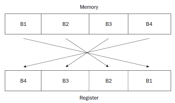
(gdb) x/x &data
0x80490bc : 0x00000225
(gdb) x/4b &data
0x80490bc : 0x25 0x02 0x00 0x00
(gdb) print/x $eax # reminding that ' print ' with no /x shows decimal value
$1 = 0x225
(gdb)
The decimal value 549 is stored in memory location data, and moved to the EAX register. The first gdb command uses the x command to display the value in memory located at the data label in hexadecimal format. The hexadecimal display shows what we would expect for the hex version of 549. The next command displays the 4 bytes that make up the integer value. Notice that the binary format version shows the 0x25 and 0x02 hex values reversed, which is what we would expect for little-endian format. The last command uses the print command to display the same value after it is loaded into the EAX register, again in hexadecimal format.
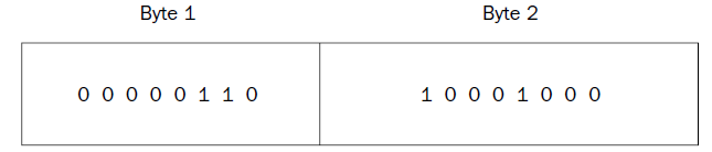 = 0x688 = 6*256+8*16+8*1 = 1672
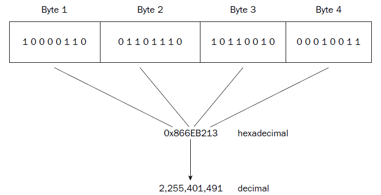
each byte is represented by a hexadecimal pair (4 bits per hexadecimal value), which are combined to form the eight-character hexadecimal value. Again, this example uses big-endian format, as seen in the register.
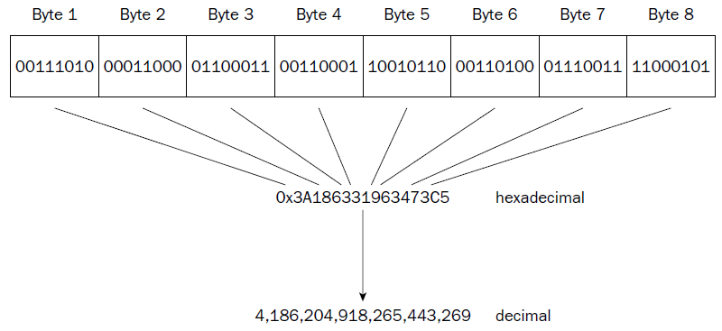
❑ Unsigned integers
❑ Signed integers
❑ Binary-coded decimal
❑ Packed binary-coded decimal
❑ Single-precision floating-point
❑ Double-precision floating-point
❑ Double-extended floating-point
the SIMD extensions on Pentium processors add other advanced numeric data types:
❑ 64-bit packed integers
❑ 128-bit packed integers
❑ 128-bit packed single-precision floating-point
❑ 128-bit packed double-precision floating-point
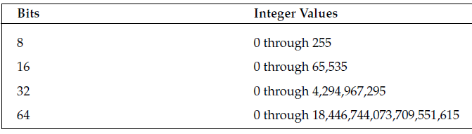
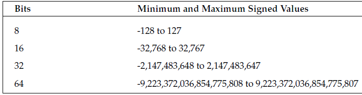
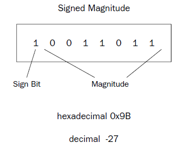 One problem with the signed magnitude method is that there are two different ways to express a zero
value: 00000000 (decimal +0) and 10000000 (decimal -0). This can complicate some mathematical processes.
Also, arithmetic using signed magnitude numbers is complicated, as adding and subtracting simple
signed integers cannot be done in the same way as unsigned numbers. For example, doing a simple
binary addition of the values 00000001 (decimal 1) and 10000001 (decimal –1) produces 10000010 (decimal
–2), which is not the correct answer. Different arithmetic instructions for signed integers and
unsigned numbers would be required on the processor.
One problem with the signed magnitude method is that there are two different ways to express a zero
value: 00000000 (decimal +0) and 10000000 (decimal -0). This can complicate some mathematical processes.
Also, arithmetic using signed magnitude numbers is complicated, as adding and subtracting simple
signed integers cannot be done in the same way as unsigned numbers. For example, doing a simple
binary addition of the values 00000001 (decimal 1) and 10000001 (decimal –1) produces 10000010 (decimal
–2), which is not the correct answer. Different arithmetic instructions for signed integers and
unsigned numbers would be required on the processor.
ONE’s complement
The one’s complement method takes the inverse of the unsigned integer value to produce the similar negative value. The inverse changes any zero bits to ones, and any ones bits to zeroes. Thus, the one’s complement of 00000001 would be 11111110. Again, as with signed magnitude numbers, one’s complement numbers have some problems when performing mathematical operations. There are two ways of representing a zero value (00000000 and 11111111), and arithmetic with one’s complement numbers is also complicated (it does not allow you to do standard binary math).
TWO’s complement
The two’s complement method solves the arithmetic problem of the signed magnitude and one’s complement methods using a simple mathematical trick. For negative integer values, a one is added to the one’s complement of the value.
For example, to find the two’s complement value for decimal -1 you would do the following: 1. Take the one’s complement of 00000001, which is 11111110.
2. Add one to the one’s complement, which is 11111111.
Doing the same for the value -2 you would get 11111110, and for -3 it would be 11111101. You may notice a trend here.
The two’s complement value counts down from 11111111 (decimal –1) until it gets to 10000000, which represents -128. Of course, for multibyte integer sizes the same principle applies across the bytes.
While this seems like an odd thing to do, it solves all of the problems in adding and subtracting signed integers. For example, adding the values 00000001 (+1) and 11111111 (-1) produces the value 00000000, along with a carry value.
The carry value is ignored in signed integer arithmetic, so the final value is indeed 0.
The same hardware can be used to add and subtract both unsigned and signed values.
When converting unsigned integer values to a larger bit size (such as converting a word to a doubleword), you must ensure that all of the leading bits are set to zero. You should not simply copy one value to the other, as shown here:
movw %ax, %bx
There is no guarantee that the upper part of the EBX register contains zeroes. To accomplish this, you must use two instructions:
movl $0, %ebx
movw %ax, %ebx
The MOVL instruction is used to load a zero value in the EBX register. This guarantees that the EBX register is completely zero. Then you can safely move the unsigned integer value in the AX register to the EBX register.
To help you in these situations, Intel provides the MOVZX instruction. This instruction moves a smallersized unsigned integer value (in either a register or a memory location) to a larger-sized unsigned integer value (only in a register).
The format of the MOVZX instruction is
movzx source, destination
where source can be an 8-bit or 16-bit register or memory location, and destination can be a 16-bit or 32-bit register. The movzxtest.s program demonstrates this instruction:
# movzxtest.s
.section .text
.globl _start
_start:
nop
movl $279, %ecx
movzx %cl, %ebx ########## ecl , ech = WRONG
// CX = 100010111 = 279
// CH = 00000001 = 1
// CL = 00010111 = 23
movl $1, %eax
int $0x80
The movzxtest.s program simply puts a large value in the ECX register, and then uses the MOVZX instruction to copy the lower 8 bits to the EBX register. Because the value placed in the ECX register used a word unsigned integer to represent it (it is larger than 255), the value in CL represents only part of the complete value. You can watch the program in the debugger and see what is happening to the registers:
$ gdb -q movzxtest
(gdb) break *_start+1
Breakpoint 1 at 0x8048075: file movzxtest.s, line 5.
(gdb) run
Starting program: /home/rich/palp/chap07/movzxtest
Breakpoint 1, _start () at movzxtest.s:5
5 movl $279, %ecx
Current language: auto; currently asm
(gdb) s
6 movzx %cl, %ebx
(gdb) s
7 movl $1, %eax
(gdb) print $ecx
$1 = 279
(gdb) print $ebx
$2 = 23
(gdb) print/x $ecx
$3 = 0x117
(gdb) print/x $ebx
$4 = 0x17
(gdb)
By printing out the decimal values of the EBX and ECX registers, you can tell right away that the unsigned integer value was not copied correctly—the original value was 279 but the new value is only 23. By displaying the values in hexadecimal, you can see what happened. The original value in hex is 0x0117, which takes a doubleword to hold. The MOVZX instruction moved just the lower byte of the ECX register, but zeroed out the remaining bytes in the EBX register, producing the 0x17 value in the EBX register.
# ch
.section .text
.globl _start
_start:
nop
movl $279, %ecx
movzx %ch, %ebx ############## 00000001
movl $1, %eax
int $0x80
C:\>gdb -q users\rnz\desktop\ch.exe
Reading symbols from users\rnz\desktop\ch.exe...done.
(gdb) break *_start+1
(gdb) run
(gdb) print $ebx
$1 = 1
(gdb) print $ch
$2 = 1
(gdb) print $ech
$3 = void
(gdb)
(gdb) print $cx
$4 = 279
(gdb) print/x $ecx
$5 = 0x117
(gdb) print/x $ebx
$6 = 0x1
(gdb) print $cl
$1 = 23
(gdb) print $ecx
$4 = 279
(gdb) print $ecl
$5 = void
Extending signed integer values is different than extending unsigned integers. Padding the high bits with zeroes will change the value of the data for negative numbers. For example, the value -1 (11111111) moved to a doubleword would yield the value 0000000011111111, which in signed integer notation would be +127, not -1. For a signed extension to work, the new bits added must be set to a one value. Thus, the new doubleword would yield the value 1111111111111111, which is the signed integer notation for the value -1, which is what it should be.
Intel has provided the MOVSX instruction to allow extending signed integers and preserving the sign. It is similar to the MOVSZ instruction, but it assumes that the bytes to be moved are in signed integer format and attempts to preserve the signed integer value for the move.
# _movsx
.section .text
.globl _start
_start:
nop
movw $-79, %cx
movl $0, %ebx
movw %cx, %bx
movsx %cx, %eax
movl $1, %eax
movl $0, %ebx
int $0x80
# _movsx in WINDOWS using MINGW-W64
.section .text
//.globl _start /*ENTRY POINT */
//_start: /*ENTRY POINT*/
nop
movw $-79, %cx
movl $0, %ebx
movw %cx, %bx
movsx %cx, %eax
movl $1, %eax
movl $0, %ebx
int $0x21
//gdb break 1
//*_start+1 not necessary
5 nop
(gdb) s
6 movw $-79, %cx
(gdb) s
7 movl $0, %ebx
(gdb) s
8 movw %cx, %bx
(gdb) s
9 movsx %cx, %eax
(gdb) info reg
eax 0x60ffcc 6356940
ecx 0x40ffb1 4259761
edx 0x401000 4198400
ebx 0xffb1 65457
esp 0x60ff74 0x60ff74
ebp 0x60ff80 0x60ff80
esi 0x401000 4198400
edi 0x401000 4198400
eip 0x40100d 0x40100d
eflags 0x246 [ PF ZF IF ]
cs 0x23 35
ss 0x2b 43
ds 0x2b 43
es 0x2b 43
fs 0x53 83
gs 0x2b 43
(gdb) print $bx
$1 = -79
(gdb) print $cx
$2 = -79
(gdb)
# mmovsx
.section .text
.globl _start
_start:
nop
movw $79, %cx
xor %ebx, %ebx ############# set to zero in every case
movw %cx, %bx
movsx %cx, %eax
movl $1, %eax
movl $0, %ebx
int $0x80
# qquad
.section .data
data1:
.int 1, -1, 463345, -333252322, 0 # every element of array has 4 bytes
data2:
.quad 1, -1, 463345, -333252322, 0 # every element has 8 bytes
.section .text
.globl _start
_start:
nop
movl $1, %eax
movl $0, %ebx
int $0x21
gdb -q users\rnz\desktop\qquad.exe
(gdb) break 1
(gdb) run
Starting program: C:\users\rnz\desktop\qquad.exe
[New Thread 440.0x260]
Breakpoint 1, start () at users\rnz\desktop\qquad.s:10
10 nop
(gdb) x/20b &data1
0x402000
0x402008
0x402010
//32 byte each element
(gdb)
(gdb) x/40b &data2
0x402014
0x40201c
0x402024
0x40202c
0x402034
//64 bit each element
(gdb)
(gdb) x/5d &data1
0x402000
0x402010
(gdb)
0x402014
0x402024
//WRONG , x/d NOT SUFFICIENT. the debugger didn’t know how to handle displaying the values using just the x/d command.
If you want to display quadword signed integer values in the debugger, you must use the gd option
(gdb)
(gdb) x/5gd &data2
0x402014
0x402024
0x402034
(gdb)
SIMD Integers
The Intel Single Instruction Multiple Data (SIMD) technology provides additional ways to define integers
These new integer types enable the processor to perform arithmetic operations on a group of multiple integers simultaneously.
The SIMD architecture uses the packed integer data type. A packed integer is a series of bytes that can represent more than one integer value. Mathematical operations can be performed on the series of bytes as a whole, working on the individual integer values within the series in parallel.
MMX integers
The Multimedia Extension (MMX) technology introduced in the Pentium MMX and Pentium II processors provided three new integer types:
❑ 64-bit packed byte integers
❑ 64-bit packed word integers
❑ 64-bit packed doubleword integers
Each of these data types provides for multiple integer data elements to be contained (or packed) in a single 64-bit MMX register.
# mmxt
.section .data
values1:
.int 1, -1
values2:
.byte 0x10, 0x05, 0xff, 0x32, 0x47, 0xe4, 0x00, 0x01
.section .text
.globl _start
_start:
nop
movq values1, %mm0
movq values2, %mm1
movl $1, %eax
movl $0, %ebx
//int $0x80 in Linux
int $0x21
(gdb) print $mm0
$1 = {uint64 = -4294967295, v2_int32 = {1, -1}, v4_int16 = {1, 0, -1, -1}, v8_int8 = {1, 0, 0, 0, -1, -1, -1, -1}}
(gdb) print/t $mm0
$3 = {uint64 = 1111111111111111111111111111111100000000000000000000000000000001, v2_int32 = {1, 11111111111111111111111111111111}, v4_int16 = {1, 0, 1111111111111111, 1111111111111111}, v8_int8 = {1, 0, 0, 0, 11111111, 11111111, 11111111, 11111111}} (gdb)
(gdb) print/x $mm0
$2 = {uint64 = 0xffffffff00000001, v2_int32 = {0x1, 0xffffffff}, v4_int16 = {0x1, 0x0, 0xffff, 0xffff}, v8_int8 = {0x1, 0x0, 0x0, 0x0, 0xff, 0xff, 0xff, 0xff}}
(gdb) print/x $mm1
$3 = {uint64 = 0x100e44732ff0510, v2_int32 = {0x32ff0510, 0x100e447}, v4_int16 = {0x510, 0x32ff, 0xe447, 0x100},
v8_int8 = {0x10, 0x5, 0xff, 0x32, 0x47, 0xe4, 0x0, 0x1}}
.byte 10, 05, 250, 32, 47, 4, 0, 1
(gdb) print $mm1
$2 = {uint64 = 72062194501158154, v2_int32 = {553256202, 16778287}, v4_int16 = {1290, 8442, 1071, 256}, v8_int8 = {10, 5, -6, 32, 47, 4, 0, 1}}
(gdb)
to be continued